Building the Gerstner model 35B Tool Chest
A Gerstner tool box has been on my wish list from about the time I started collecting the various small tools involved in watchmaking and machining. Relatively recently, Gerstner began to offer a selection of their tool boxes in a “build-your-own” kit form. The kit includes all the necessary hardware along with the lumber already machined and ready to be fit and glued together. This allows for a significantly lower price tag compared to their finished chests, and during one of their warehouse sales, I decided to give it a try. Having the wood already machined provides for a fun and relatively straightforward project for those of us whose woodworking competence or resources do not allow for making one ab initio. I selected the model 35B (now sold as Model # 1607), which is a seven drawer case, made of oak with nickel hardware. The kit is supplied with directions for its construction and I'll note where I've deviated (intentionally or unintentionally) or, in retrospect, think one should do so. There are also a few YouTube videos produced by Gerstner that provide some guidance for the various construction steps for this particular tool chest.
Instructions
http://gerstnerusa.com/image/data/pdf/B35A-B35B_kit_base_instructions.pdf
Gerstner videos on Youtube
Pre-assembly demonstration
Drawer assembly and fit
Chest and front lid assembly
Wiping stain demonstration
Installing front lid
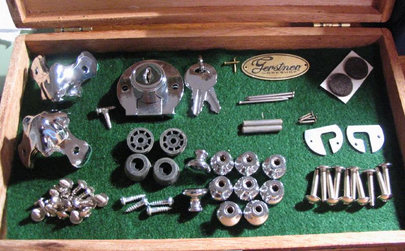
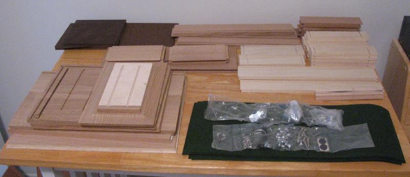
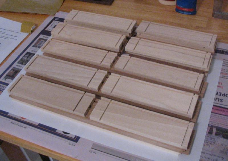
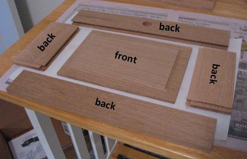
Upon arrival, the box was unpacked and the parts laid out to double check the inventory. Just in case the photo is confusing, a cigar box that just happened to have a piece of green felt was used to temporarily store the hardware.
Instructions
http://gerstnerusa.com/image/data/pdf/B35A-B35B_kit_base_instructions.pdf
Gerstner videos on Youtube
Pre-assembly demonstration
Drawer assembly and fit
Chest and front lid assembly
Wiping stain demonstration
Installing front lid
Upon arrival, the box was unpacked and the parts laid out to double check the inventory. Just in case the photo is confusing, a cigar box that just happened to have a piece of green felt was used to temporarily store the hardware.

|
|
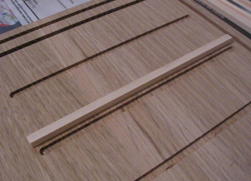
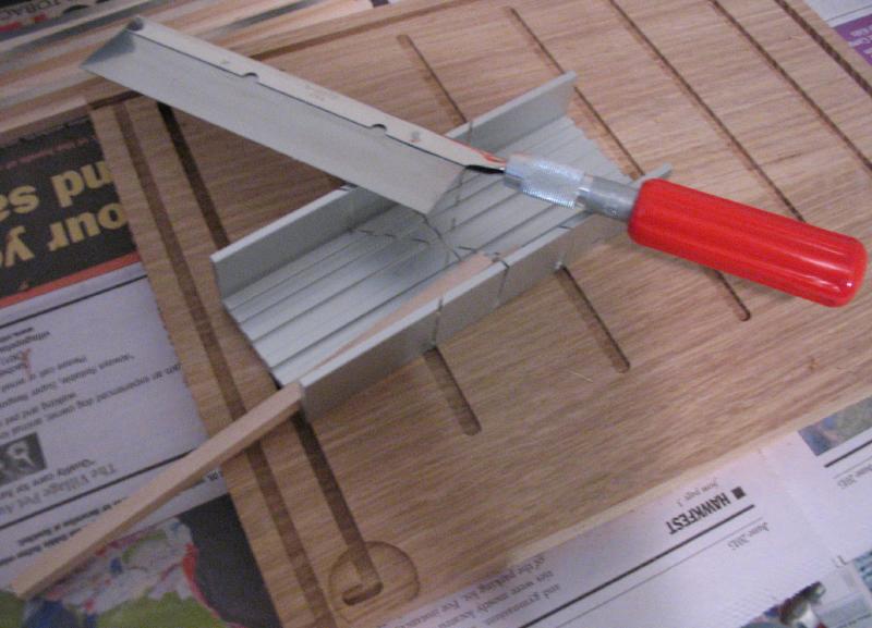
The first step is to insert the drawer rails into both the side panels and into the central divider. The kit includes square strips of wood to be used as the rails. They are a slightly oversized fit to the milled channels, so a short section must be sawed off in order for them to fit. I used a small miter box and an X-ACTO razor saw to trim them to length. The strips were then lightly sanded on 220 grit paper to remove the rag left from sawing and to generally smooth the surfaces of the strip. The strips that go into the central divider needed to be cut a little shorter than those in the side panels. Prior to gluing the strips in place, all of the milled channels were sanded with a piece of folded-up 220 grit sandpaper in order to remove the rag left from the milling process. The various milled channels and sawn edges of all the parts in the kit are in need of sanding in order to provide a proper fit, but I may not note it every time this task was done. However, just about everything will need some degree of sanding at one point or another before the work is completed.
|
|
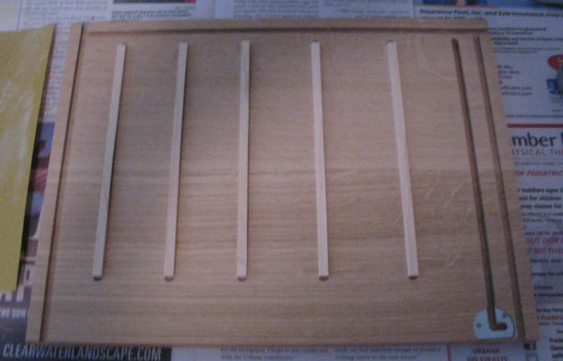
A bead of wood glue was applied to a milled channel and the wood strip inserted and aligned. The strip should be 1.5 inches from the front edge. Once aligned correctly, the strip was tapped in with a small hammer and the excess glue that emerged was wiped off. I am using Elmer’s brand wood glue, however, I think just about any wood glue will do.
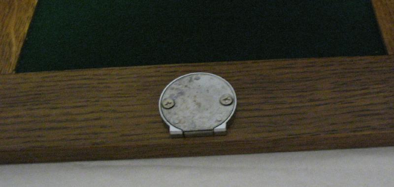
The ‘lid slide plates,’ which are metal reinforcements for the pivot-point of the front lid hinge pins, were aligned and nailed in place on each of the side panels. It is important that the alignment is correct and maintained while nailing them in place so as to allow the hinge pins to move freely through the channel in use.
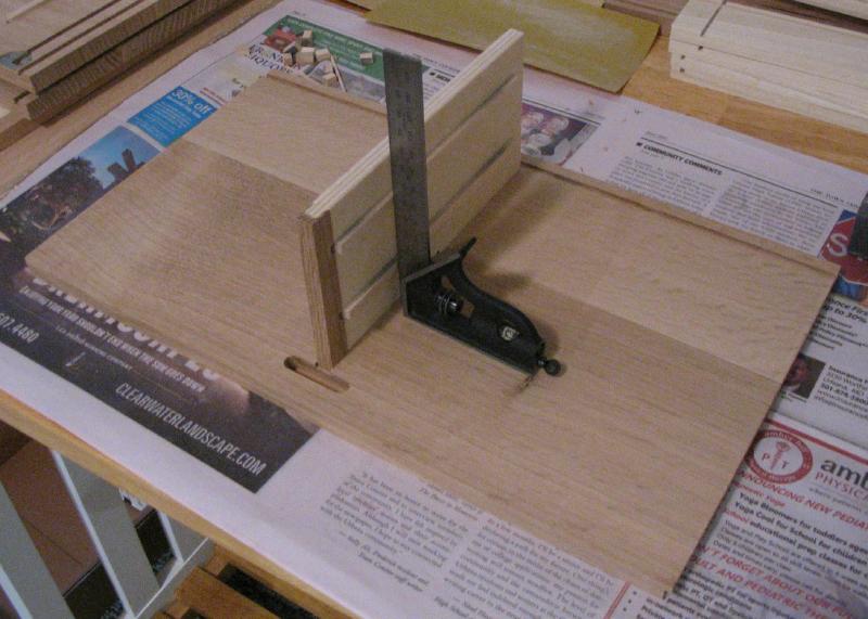
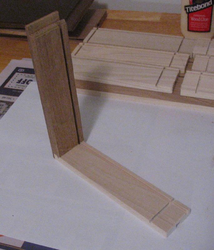
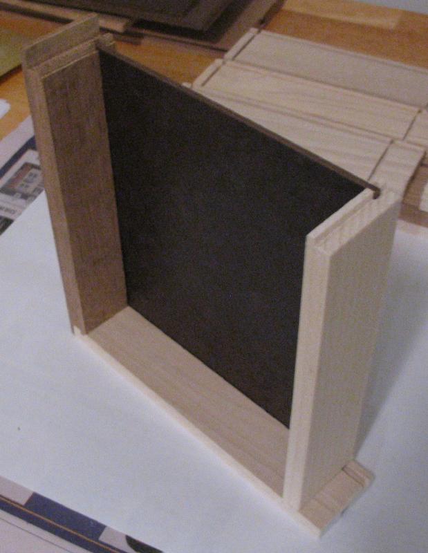
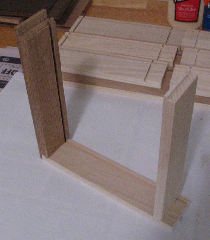
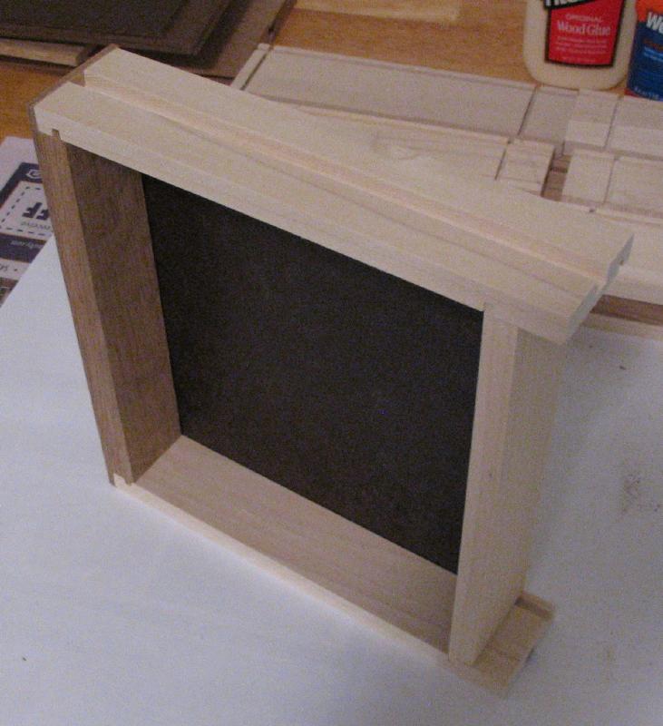
The central divider is made of birch plywood with an oak strip attached at the front. The drawer slides are glued into both sides of the divider and then it is glued into the top panel of the case. The edge of the divider should be about one inch from the front and especially needs to be clear of the milled recess for the locking mechanism. A combination square was used to assure that the divider was positioned at a 90 degree angle to the top panel. It was allowed to dry and cure without clamping.
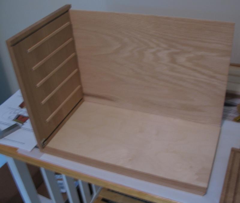
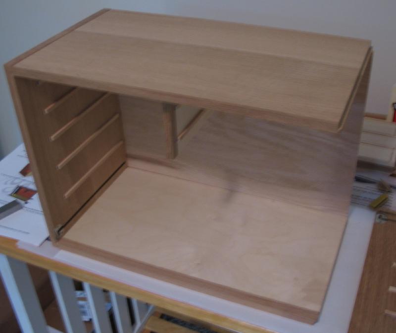
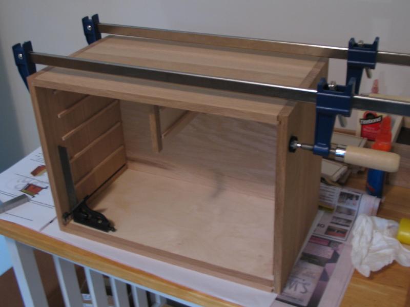
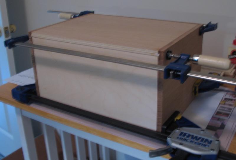
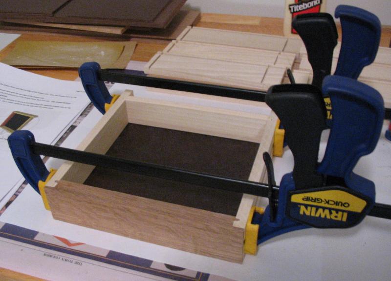
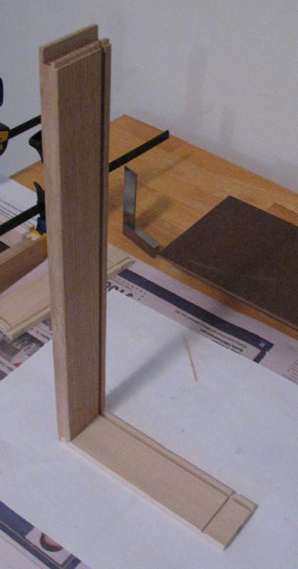
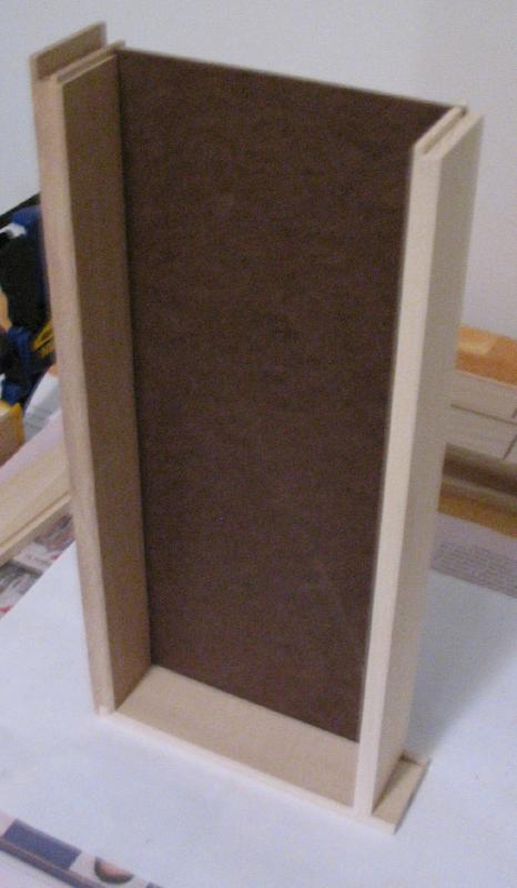
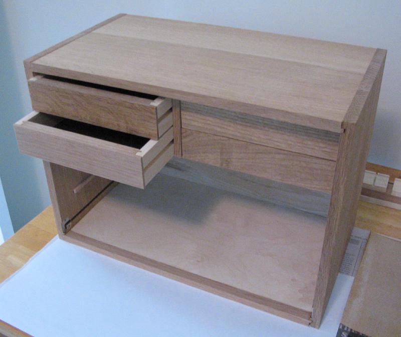
The joinery of the case components was sanded and the case then dry-fit to check alignments and to familiarize myself with their orientations. The instructions included with the kit demonstrate assembling the case starting with one side lying flat and ending with the second side being fitted to the assembled case. While dry-fitting, I found that I was not able to reposition the case for clamping without everything coming apart. The case was therefore built in an upright fashion, starting with the base, side, and back panels. The top was added, and finally the other side panel. The grooves in the side panels and the top-to-back panel groove were glued. Two 24” clamps were attached to the case, and it was then repositioned onto its front for adding two additional clamps. I used two rather oversized clamps for this, and the location of one of the 24” clamps was changed so that the lighter-weight clamps were on top.
|
|
|
|
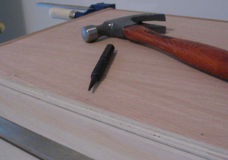
After clamping and checking that things are still square, the back panel of the case is secured to the base panel using the three finishing nails supplied in the kit. They were equally spaced out (~3.75”), and hammered-in just below the surface of the wood using a nail-set.
The components of the seven drawers were sorted into piles of respective parts prior to assembly. The joinery of each drawer component needed to be sanded lightly (150-220 grit) to provide a good mating. Each drawer was dry-fit together first and checked with the square prior to gluing together.
*Note: Although not stated in my set of instructions and therefore not done here, it would be advisable to drill the holes for the knob hardware before gluing the drawers together. The holes can then be countersunk on the interior face to allow the screw head to be below the surface of the wood. This is largely cosmetic, but also would prevent the contents of the drawer coming into contact with the metal screw head.
The assembly process starts with (1) the right side piece and the oak front piece, which is attached with glue spread on the joint of the front piece. The drawer bottom is free-floating within the drawer frame, so an attempt was made to keep glue out of these channels. (2) The back was then added to the drawer, (3) followed by sliding the Masonite drawer bottom into place. (4) The second, left-side piece was then attached with glue on both the front and rear joints, and (5) the completed assembly was clamped together from side-to-side with 12” clamps. (6) All the corners were checked with the square and the clamping adjusted accordingly. Only light clamping pressure is required, and over clamping tends to distort the ‘squareness.’ I only had two 12” clamps, and I allowed the glue to cure overnight, so only one drawer could be assembled per day. However, this leaves ample time to prepare and dry-fit the next drawer!
|

|
The three larger drawers were assembled in essentially the same manner as the smaller ones; however, they require clamps with a larger span. I used two, 24” clamps for each assembly.
|
|
|
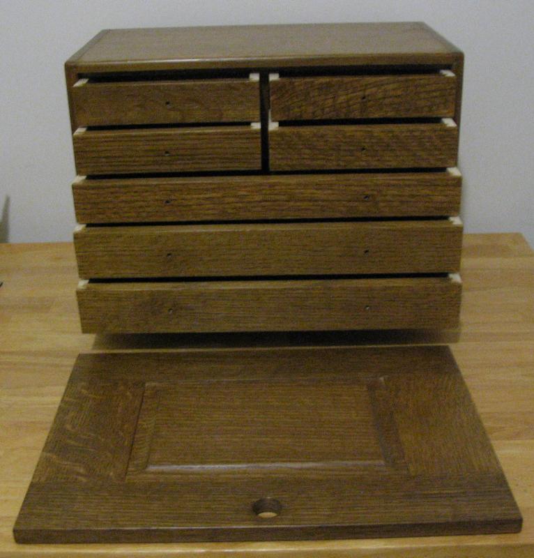
Once the drawers have dried and cured, they are individually tried in the case to determine the best suited position for each (obviously, the options are somewhat limited). Some fitting was required for a couple of the drawers in order to provide a smooth sliding action without any binding. These adjustments were made to the sides of the drawer by rubbing on 220 grit sandpaper that was lying on the benchtop. Once a good fit is achieved and the positions for the drawers are determined, they are numbered in pencil on the back panel of each drawer for future reference. Of course, one must decide and remember the numbering sequence that will be used for the top four drawers (i.e. a ‘Z’ pattern or ‘И’ pattern; I chose the latter). The edges of the drawer faces need to be sanded down to provide spacing between the drawers. This was kept fairly minimal (about 1/16"), but it is needed to allow for possible expansion of the wood due to changes in humidity, etc.
|
|
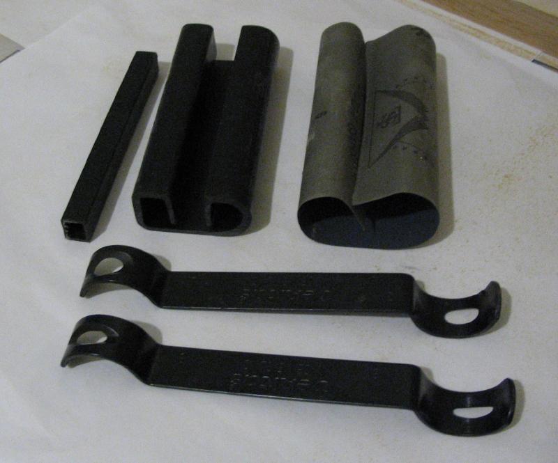
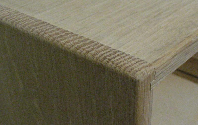
All of the exterior corners of the case need to be rounded over in order to best fit the corner hardware supplied by Gerstner, which is designed to fit a 3/16” radius. A router with a round-over bit would likely make easy work of this step, however, a simpler tool was employed. I used a set of cornering tools made by Veritas. The set consists of two double-sided scrapers with rounded cutting edges of 1/16” to 1/4” radius. The set includes a honing jig that can be wrapped in emery paper and the cutting edges sharpened on the respective radius of the jig. For cornering the case, I found they work best by starting with the 1/16”, followed by the 1/8” and then the 3/16” tool. They work fairly well, however, some attention to grain direction is needed as the tools have a tendency to ‘dig-in’ and will remove more material than desired or worse, leave a gouge that must be sanded down to even it out. Surprisingly, the tools even worked well on the end-grain of the left and right top corners.
|
|
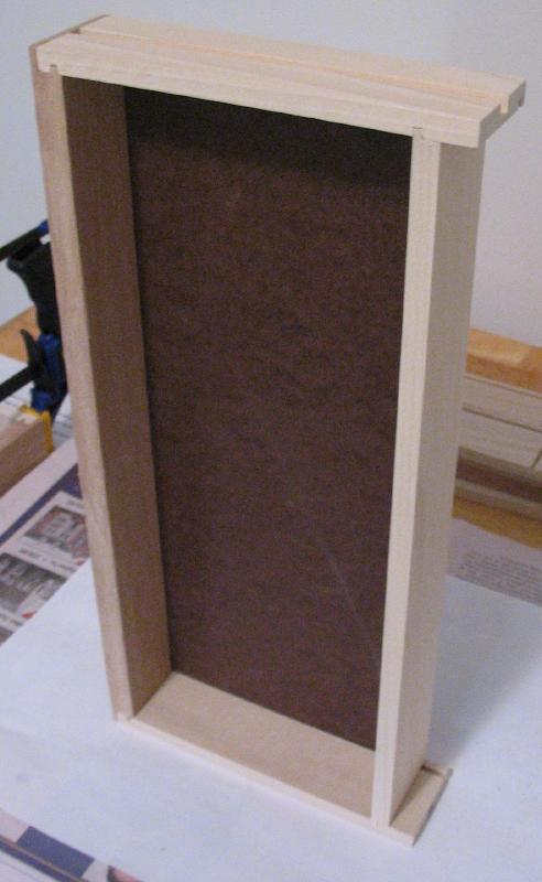
The case lid panel was laid out and the joinery sanded to provide a good dry fit. There was a fair amount of sawing rag and residual chips of wood left from the machining operations that needed to be removed, but this was cleaned up with 150 and 220 grit sandpaper. The central panel is free floating in the finished lid assembly, so the portion of the joinery that captures the panel was not glued. Assembly: first a bead of glue was applied to the bottom rail for a length somewhat less than the width of the left stile joint, and the two pieces are then mated together. The center panel was inserted and used for alignment of the remaining components. The bottom rail groove was glued on the right side and the second stile was inserted into position. Finally, the top rail was glued in the groove on the left and right sides and put into place, thereby completing the lid. The work was then clamped, from top to bottom, using two 12” clamps.
Although it is not explicitly stated in the instructions, Gerstner marks the front side of each of the lid rails in pencil. This is represented in the illustration in their instructions. That being said, I confidently assumed that the pencil marks indicated the back/interior side of the lid and assembled it only to discover the error the following day after the glue had long since cured. This results in the center panel being slightly raised above the plane of the rails. There is not much that can be done to correct this, other than sawing the frame open and then attempting to repair it afterward. I decided to use it as is, and sanded the center panel down slightly to make the error less pronounced. The lid will still function for its intended purpose.
|

|
At this point everything can be thoroughly sanded. I used a 60 grit paper for coarse removal of some protruding and uneven edges, etc. Gerstner recommends at least a 150 grit finish, however, everything was then sanded with 150 grit, 220 grit, and then finished with 320 grit.
|
|
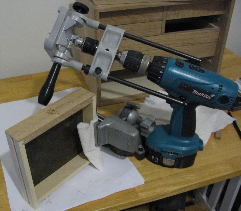
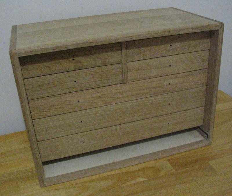
The holes for the hinge pins in the front lid were drilled 5/32” at the specified location (centered and 19/64” from the bottom). My setup for this operation was less than perfect: the lid was held on its edge using a small adjustable vise and the holes drilled free-hand with a hand drill.
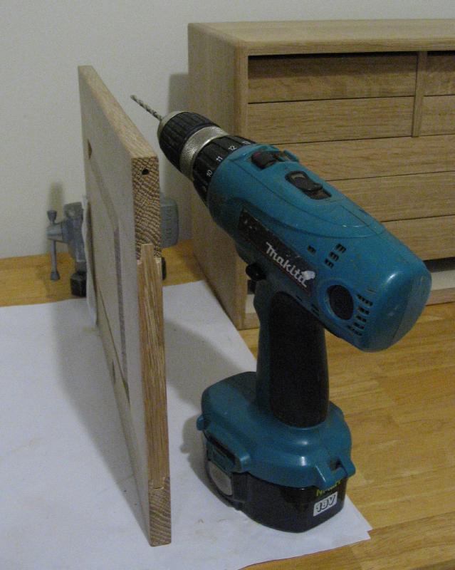
Likewise, the centered locations for the drawer hardware were found simply by measuring and marking in pencil, and then drilled through 5/32” using a hand drill along with a guide adapter that simply helps to keep the drill perpendicular to the drawer face.
As noted above, it would be advisable to drill the holes for the hardware before gluing the drawers together. In addition, some type of alignment jig with a drill press would assist in the holes being drilled in a more uniformly centered fashion. I did a half decent job marking and drilling free-hand, but at least one is a little off center...
|
|
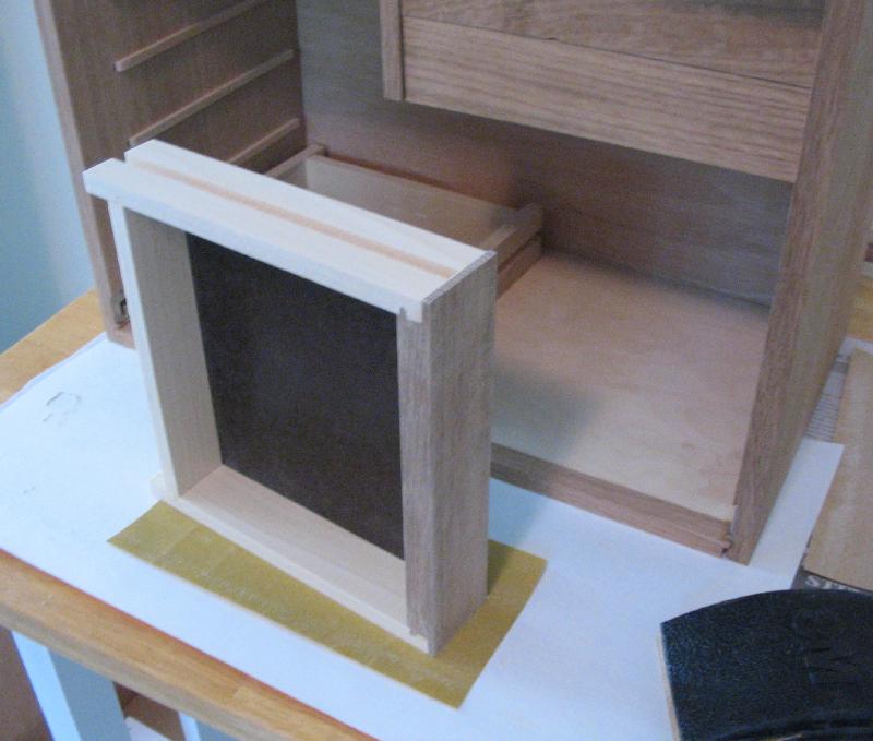
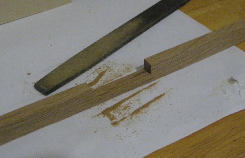
Next, the stop piece for the front lid cover is glued into place. It must first be test fit such that the lid will rest flush with the sides of the case when closed. This required a fair amount of sanding to reduce the width the stop piece. The cut-out portion of the stop piece required some filing to remove machining marks left from the manufacturing process. It was glued into place and allowed to cure before staining.
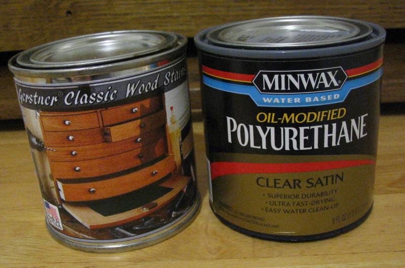
All the oak surfaces were stained using a "golden oak" color stain obtained from Gerstner, which they state is one of the same stains used in house. The stain was applied with a cotton cloth and the excess wiped off. The soft wood and ply wood that composes the drawer sides and other parts of the case do not accept the stain very well, so these parts were generally avoided, but I will admit that did not always go as easily as planned. After drying overnight, a light coating of Minwax, water based, "oil-modified," "clear satin" polyurethane was applied with a soft bristle, nylon brush. Two additional coats were applied after curing overnight and light sanding with 320 grit sandpaper in between. There are, of course, countless choices of stain and varnish combinations to choose from, and Gerstner notes that after staining they apply 1 to 2 coats of lacquer sealer followed by 1 to 2 coats of lacquer. However, the water based polyurethane is easy to work with and leaves a finish that meets my needs.
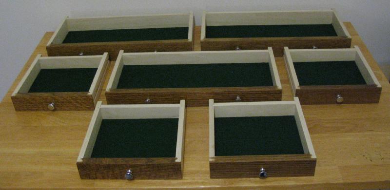
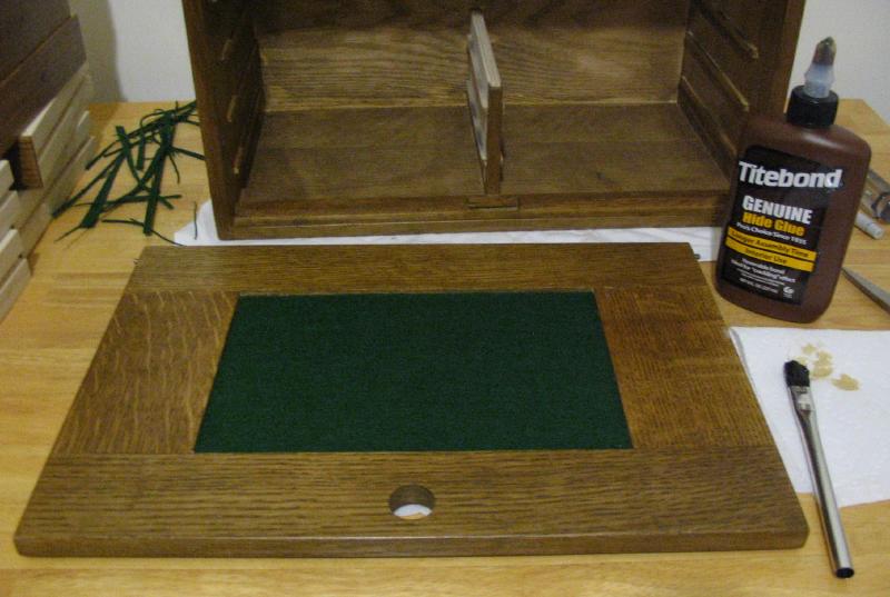
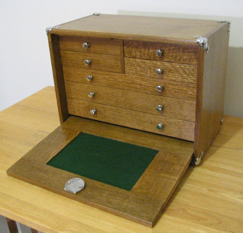
The interior drawer bottoms as well as the center portion of the front lid are lined with felt, which is supplied with the kit, but needs to be cut to fit. Fortunately, they provided some extra lengths of felt since my first attempt was not quite right. I found that an accurate method was to first square two edges of the felt to match a corner of the drawer and then trim to width and square with the next corner, and then finally trimming to length. I used ordinary office scissors, and imagine some type of shear that can cut a straight and even line would make things more tidy. The instructions suggest animal hide glue mixed with water as the appropriate adhesive, and I suspect this is to allow for an easier separation later (or when) the felt needs replacing. Instead, I am using Titebond brand of ready-made "hide glue." The glue was spread onto the surface with a small brush and the felt put into place. The felt was smoothed out with a small piece of smooth plastic to remove any wrinkles or air bubbles. The drawer knobs were fastened into place while I was at it.
|
|
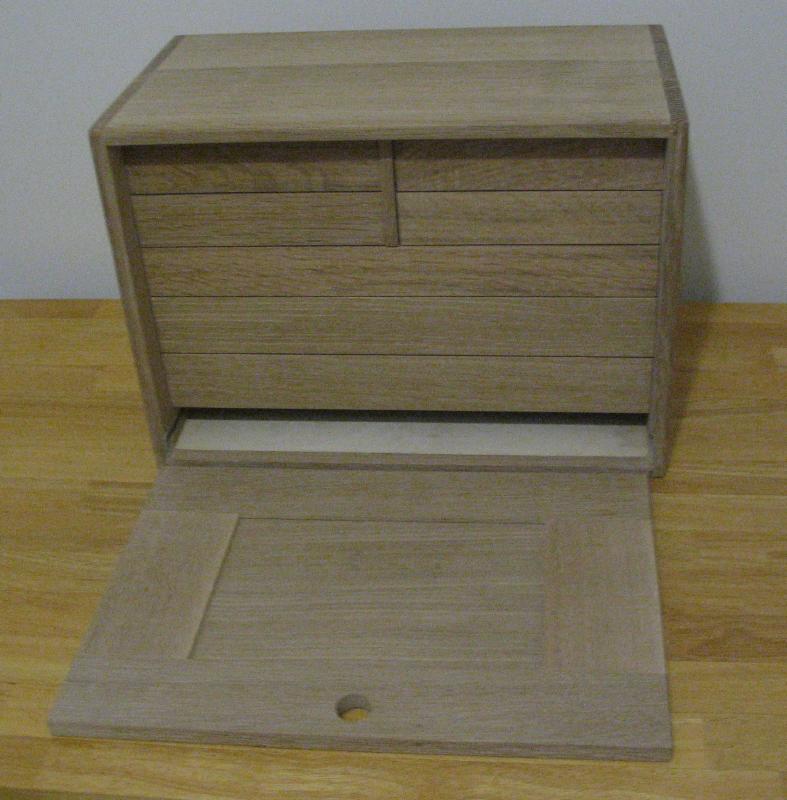
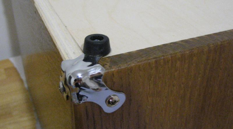
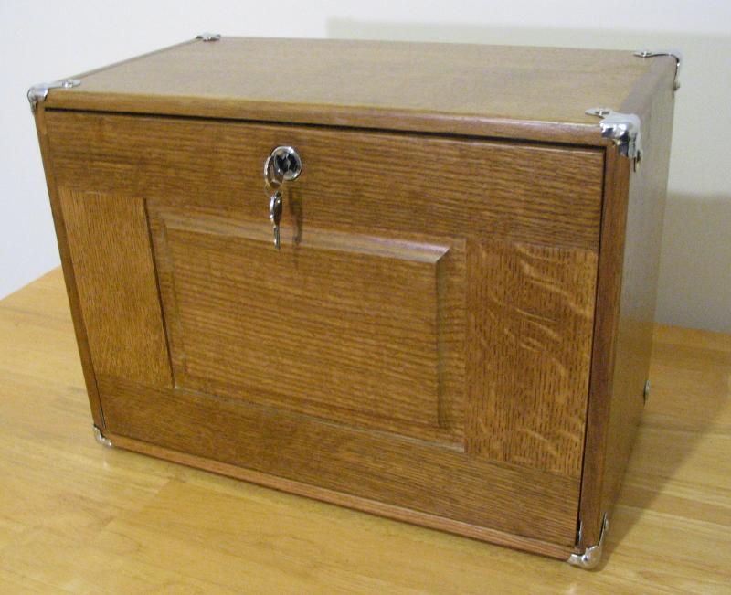
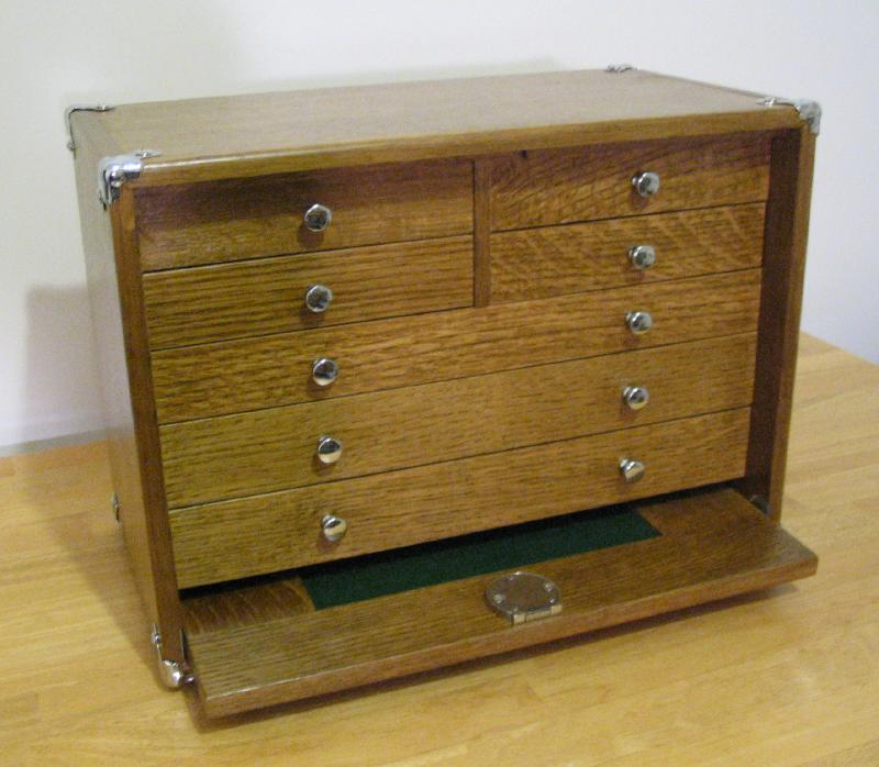
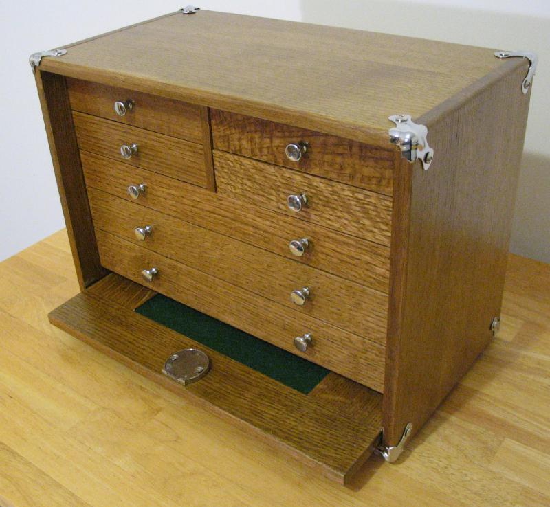
All that remains now is to attach the various pieces of hardware. Four rubber feet are screwed into the bottom of the case. The instructions were not exactly clear to me, but based on an accounting of the hardware included and placement of the corner protectors, I concluded the feet are attached to the case sharing holes with the corner protectors and using the four 1/2" screws. The remaining corner protectors are screwed into place; and I found drilling a shallow 1/16" pilot hole helped start the screws in the intended locations. The locking mechanism is installed into the opening in the lid, and the hinge pins are tapped into the holes previously drilled with about 1/8" still extending out. Two felt discs with adhesive backing are fixed within the case about 3/4" in from the front edge so that the lid and case will not directly rub against one another. The lid can then be installed, something which Gerstner has a Youtube video dedicated to demonstrating how to do, however, one hinge pin is placed into the pivot point of the slot and the lid angled and maneuvered to get the second pin into its slot as well. The last piece of hardware is a "Gerstner Workshop" nameplate that is intended to be nailed into the face of a drawer, however, I have not decided whether to do so just yet...
|
|
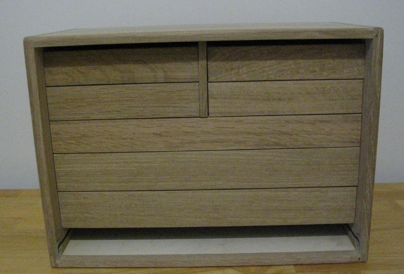
The toolbox is now ready to be put into service and likely filled to capacity in short order! It took more effort to get it all together and there were more stumbles along the way than expected, but it was an enjoyable project and leaves one appreciating it all the more.
|
|
