The Mainsprings
Daniels gives a good, basic description of mainspring theory and application to watches in Chapter 9. This watch is designed to have six turns of winding, and four of which are used to drive the watch for 32 hours. Following the formulæ in this chapter...
Divide available barrel space into 100 parts
21.3mm ÷ 100 = 0.213mm
One third of the space is occupied by the arbor hub (33 parts), leaving 66 parts available for spring.
26 parts = 5.538mm
41 parts = 8.733mm
The difference is 3.195mm which is 1.5975mm on each side of the arbor.
To find the theoretical spring thickness:
1.5975mm ÷ 6 turns = 0.26625mm
I mentioned in the post on making the barrels that I have been having some difficulty finding a source of mainsprings anywhere close to the required dimensions. Searching for spring manufacturers, I was able to order some stock tempered carbon steel spring that was reasonable close, hopefully it will work out... They are 30" lengths of 0.120" x 0.010". 0.120" is 3.048mm, which is 0.052mm shorter than suggested clearance of 0.1mm (Joseph Bulova - Watchmaking Handbook).
0.010" is 0.254mm, a tad less than calculated, so 1.5975 ÷ 0.254mm = 6.289 available turns.
Determination of the theoretical length. Daniels does not really discuss this, which leaves me a bit confused. I found a set of calculations and determined the length needed as follows:
1. Divide ID of barrel by 2: 21.3 ÷ 2 = 10.65
2. Square no.1: 113.4225
3. Multiply no.2 by pi: 356.327
4. Divide arbor diameter by 2: 7.1 ÷ 2 = 3.65
5. Square no.4: 13.3225
6. Multiply no.5 by pi: 41.854
7. Subtract no.6 from no.3: 314.473
8. Divide by 2: 157.2366
9. Divide spring thickness in no.8: 619.0417mm = 24.37"
I will need to trim the length, form the attachment points in the spring, and form the inner coils.
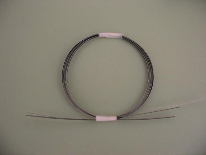
The spring stock as it arrived from the manufacturer.
Cutting to Length
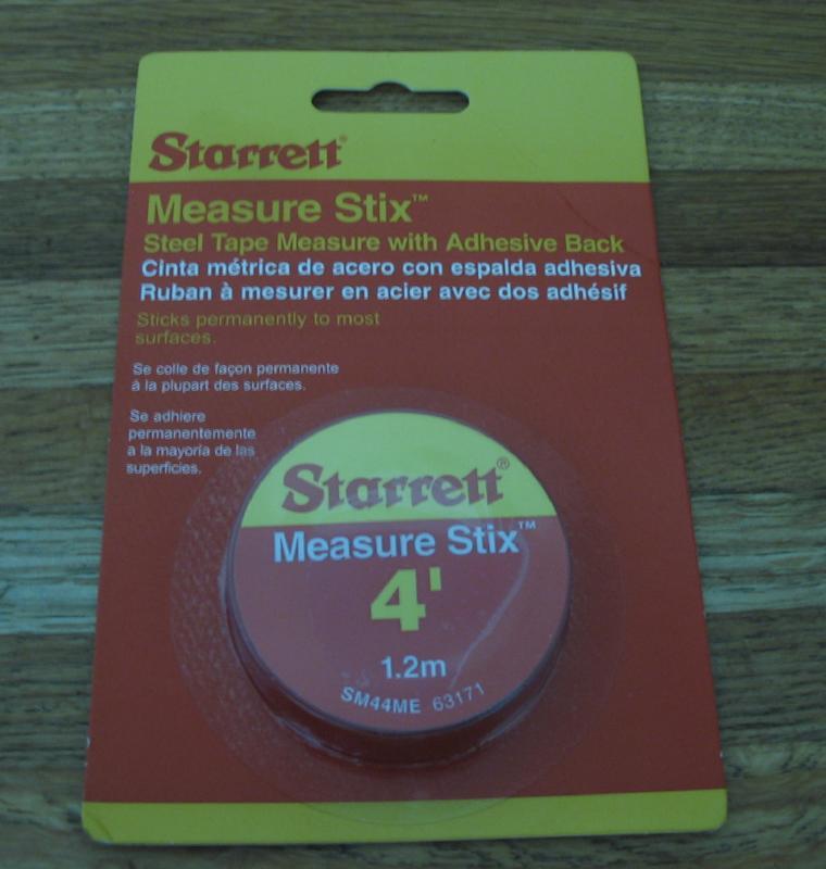
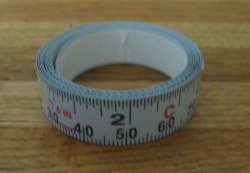
I purchased Starrett SM44ME, their metric version of the 'Measure Stix' product. It is a steel tape measure with adhesive backing. It is graduated to millimeters and 1/16" for 4 feet (1.2 meters). I adhered it to a 4' length of 1/8"x1" aluminum bar.
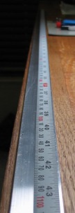 |
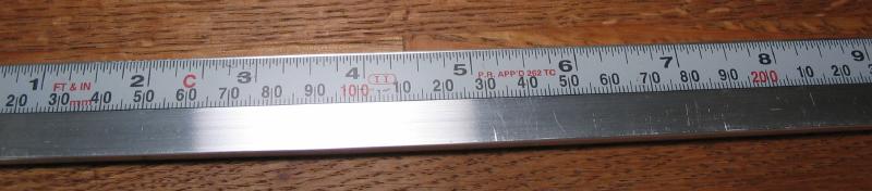 Not easy to photograph |
Punching for the Hooks
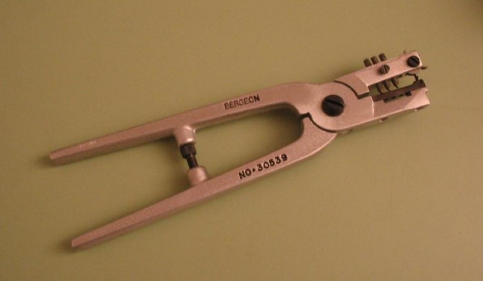
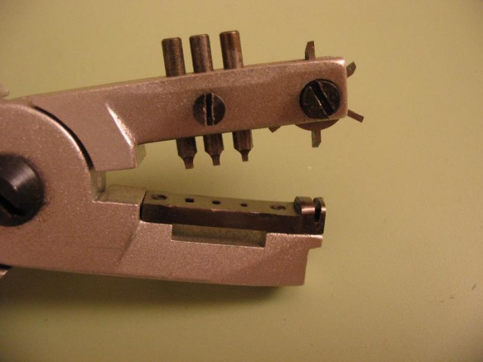
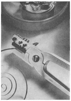
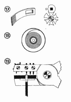
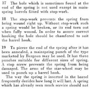
Some instructions for using the spring punch, and general information assuring me that a hole end spring is appropriate for a barrel with stop-work, can be found in Hans Jendritzski's "The Swiss Watch Repairers Manual." An excellent book which does not get much recognition here in the U.S.
 |
 |
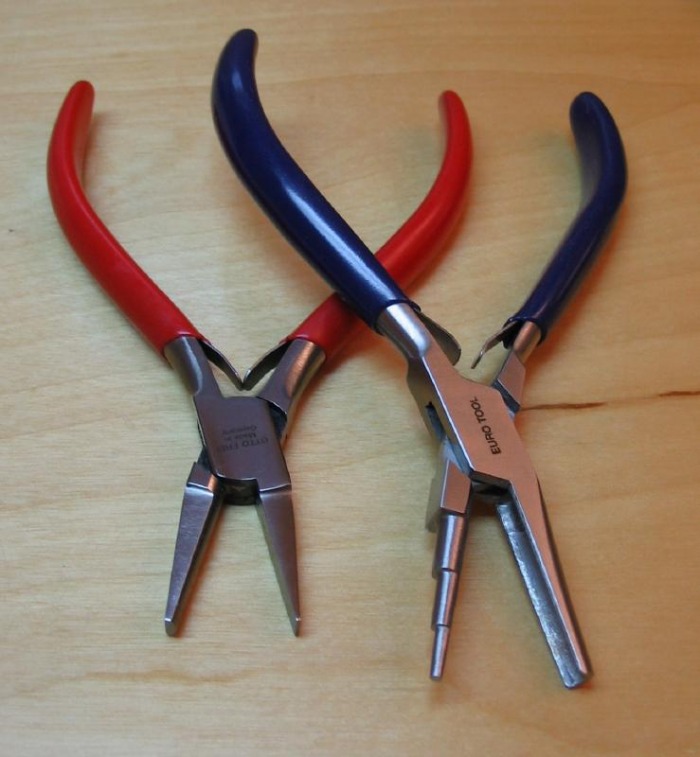
Forming the inner coil of the mainspring and any other bending required is facilitated with forming pliers. Shown are a pair of German ring bending pliers with one rounded jaw and one flat, to assist in forming gentle curves. The other are coil bending pliers, which has a graduated round jaw and a U-shaped jaw for forming tight turns. The large section of jaw is approxiamtely the same diameter as the barrel arbor hub, so it works well for forming the inner coil of the sping.
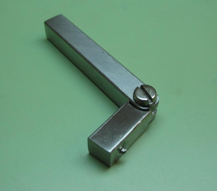
I didn't own a mainspring winder large enough to handle springs of this size. I decided to make a set of tooling to allow springs to be wound on the lathe. First a hinged hook to hold the outer end of the spring was made to fit the tool post. It is made from 1/4" keystock and a simple hinge was milled into it. A hook pin was made to fit the end piece.
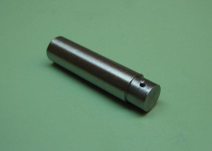
The arbor is made from 8mm O-1 drill rod, turned to match the barrel arbor hub diameter (7.1mm) and drilled to accept a blued steel pin which mates with the mainspring. In practice the arbor is simply mounted in the lathe chuck and the spring wound onto the arbor by rotating the headstock, which can then be locked when fully wound.
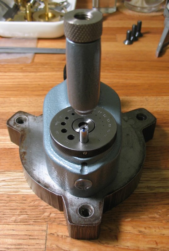
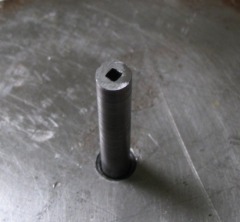
A winding square is made for the headstock to wind the mainspring onto the barrel arbor directly. 5mm O-1 drill rod was given a square hole using a punch as before. The length of drill rod was selected to pass through the staking tool and be supported on a steel block.
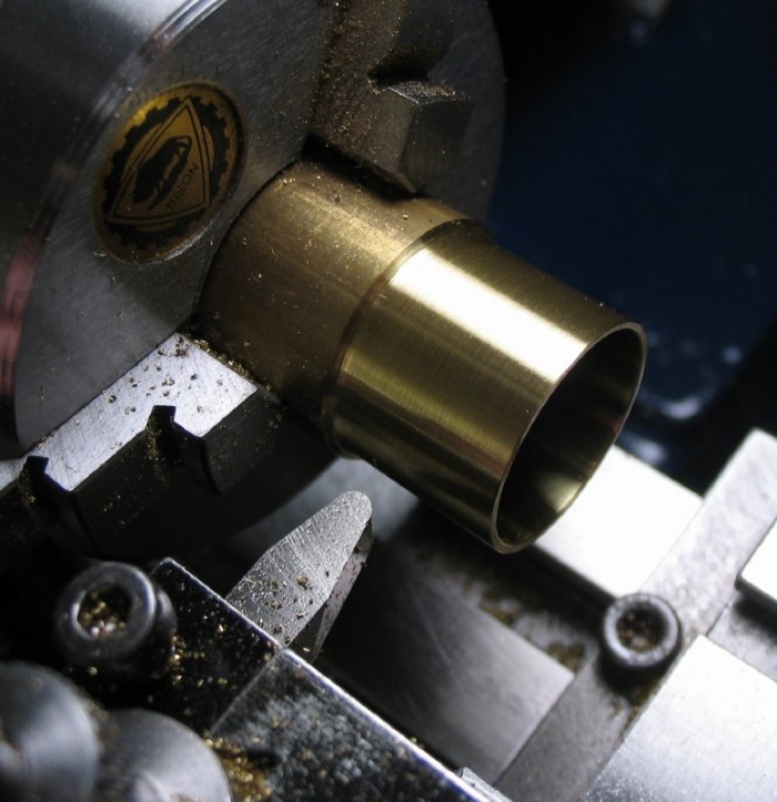
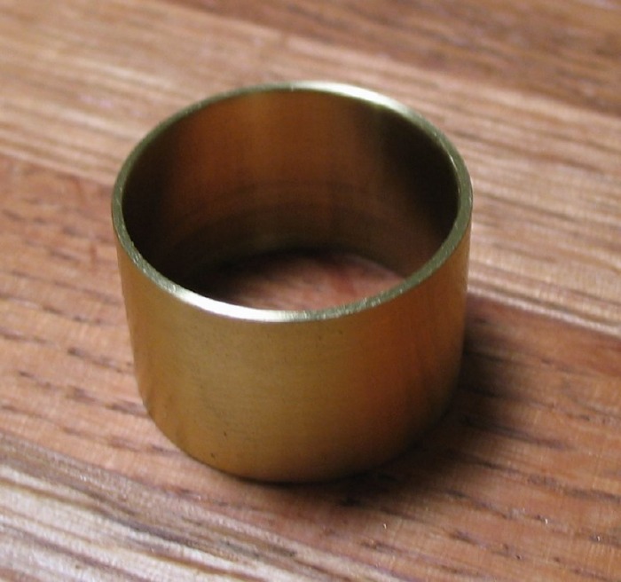
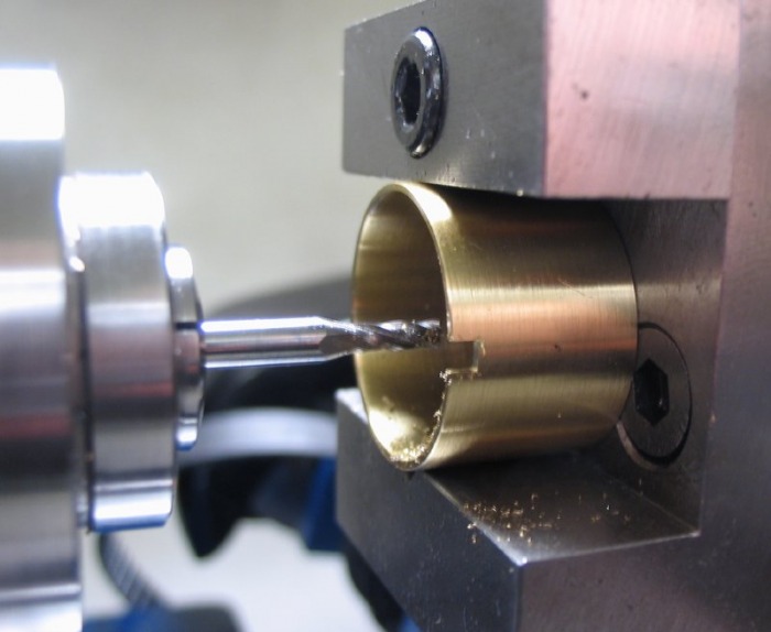
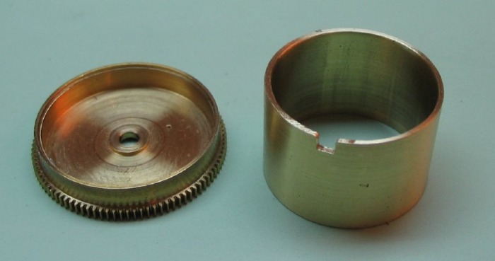
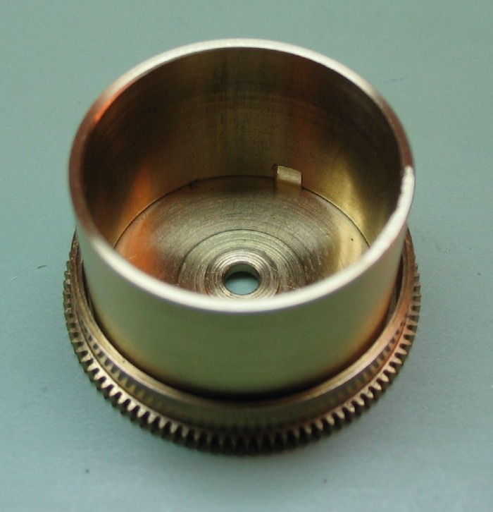
The keeper sleeve was made from 0.875" x 0.065" wall brass tubing. It was turned down to about 20mm in outside diameter. A 2mm wide x 3mm deep notch was milled in the edge to expose the end of the spring during winding. The corner of the notch was rounded over to prevent any stress on the spring.