
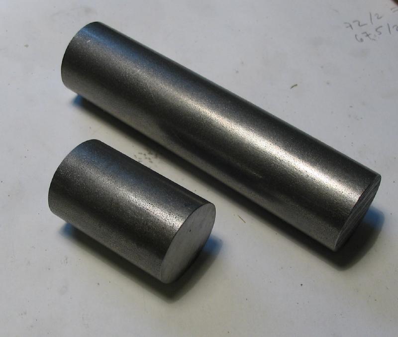
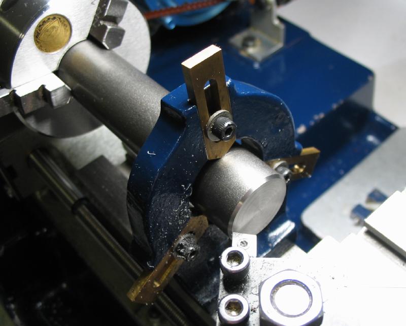
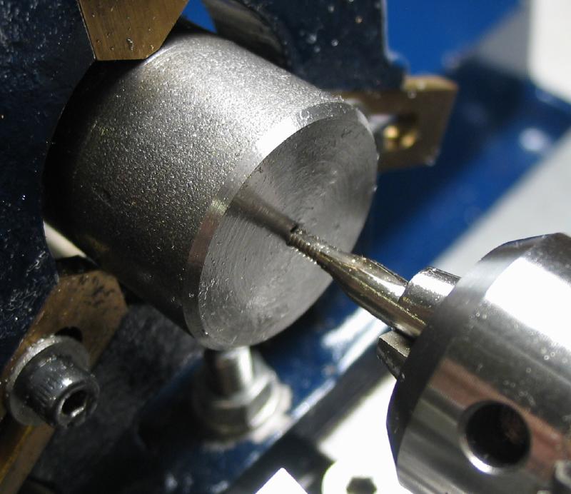
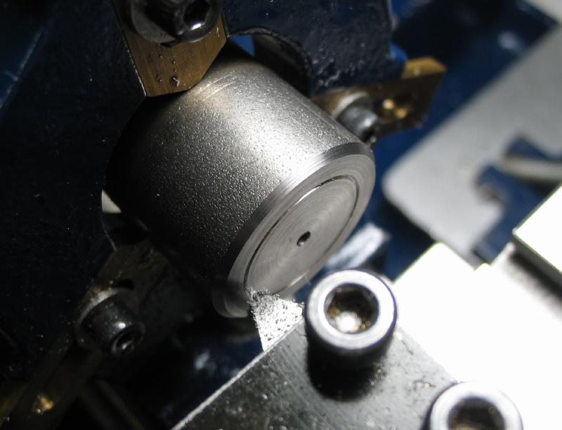
The weights are relatively simple and made from mild steel round stock. The rod is sawed off close to the final length and the end faces turned and chamfered. The longer weight required the use of the steady rest to support the work on the lathe. The top face is drilled and tapped M2 to attach the hook made below. A decorative groove was turned and the the sides of the steel stock was given a light treatment with emery paper to improve the finish but the rough, somewhat pitted finish of the raw stock was retained.
|

|
|
|
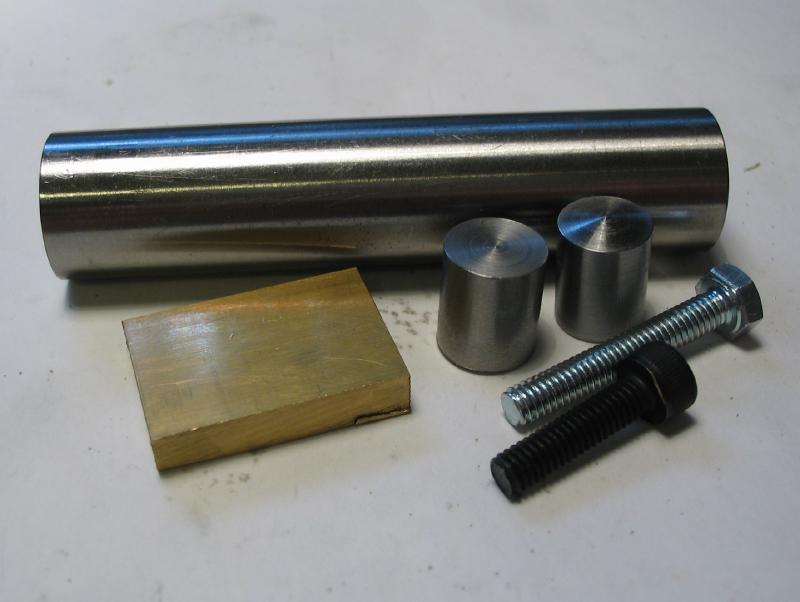
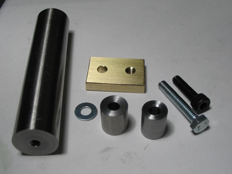
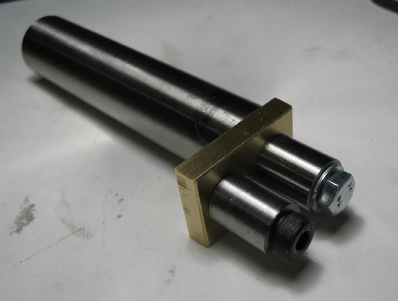
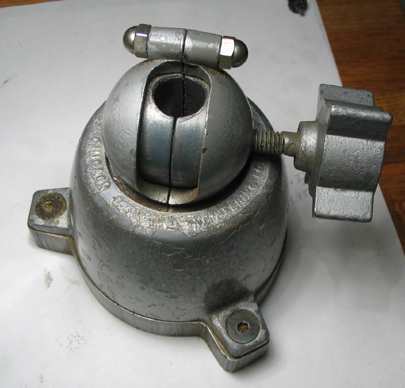
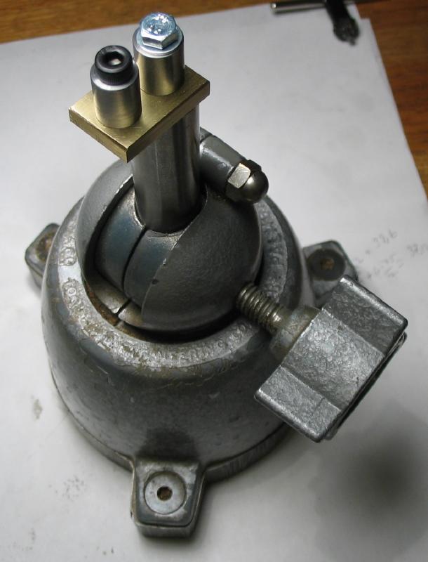
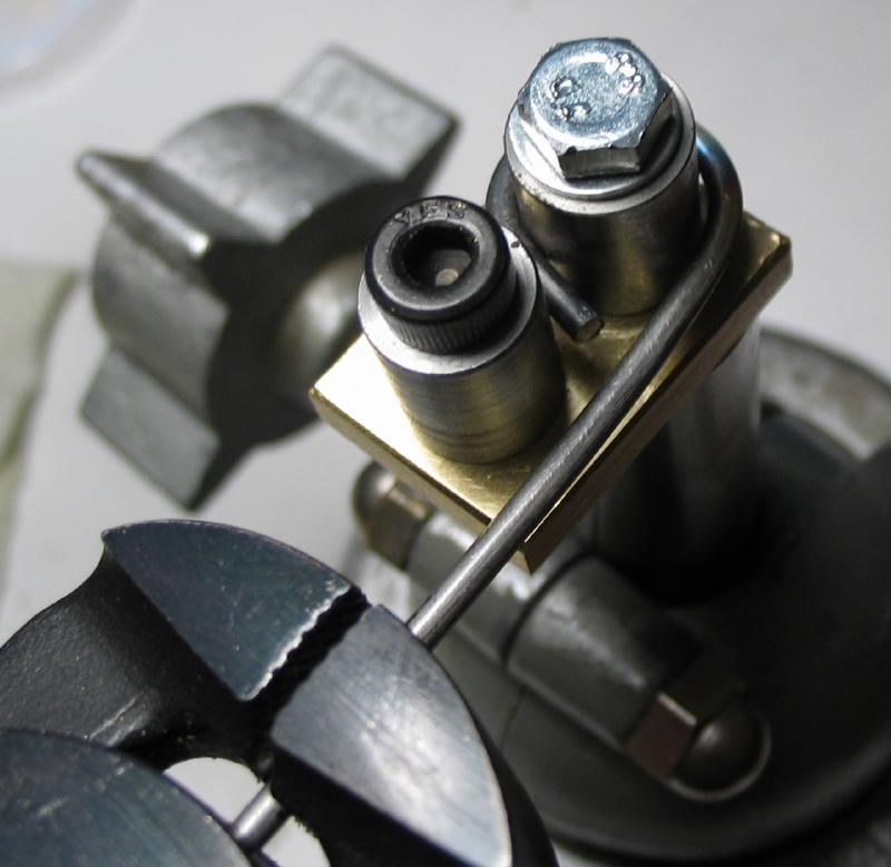
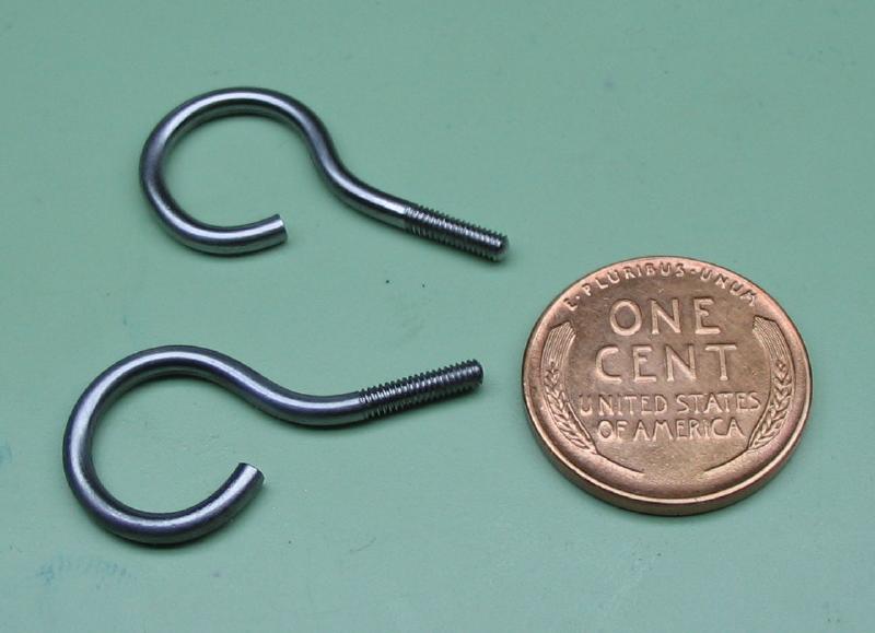
The hooks for the weights were fashioned from 'low-carbon' steel rod that is 2mm diameter (measures 1.95mm). The method for bending the wire to the desired shape consists primarily of two pins that are about 10 and 9.3 mm in diameter. Before and after photos are shown, and the two pins and brass plate were pieces from the scrap box. The pins are spaced to allow the steel wire to fit between them, and the parts are drilled and tapped as needed to assembly with two M4 screws. The post is made from 5/8" diameter rod in order fit in the base of my adjustable vise.
|
|
|
|
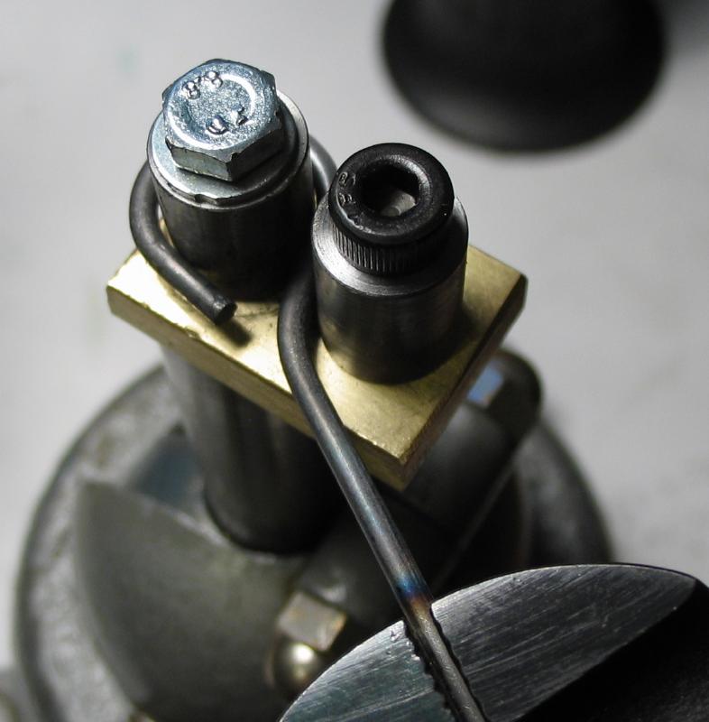
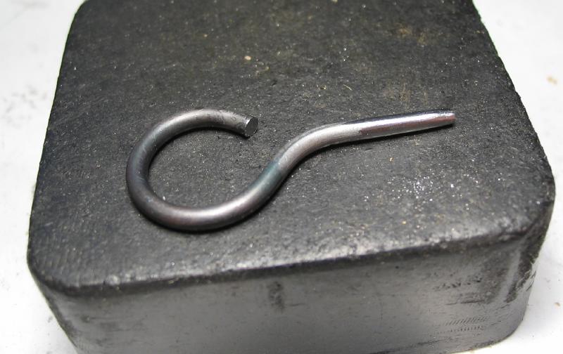
The wire was held in a hand vise and heated to about red hot in order to soften the wire for easy bending. The bends were carried out in two steps, first to form the loop followed by a reverse bend to straighten out.
|
|
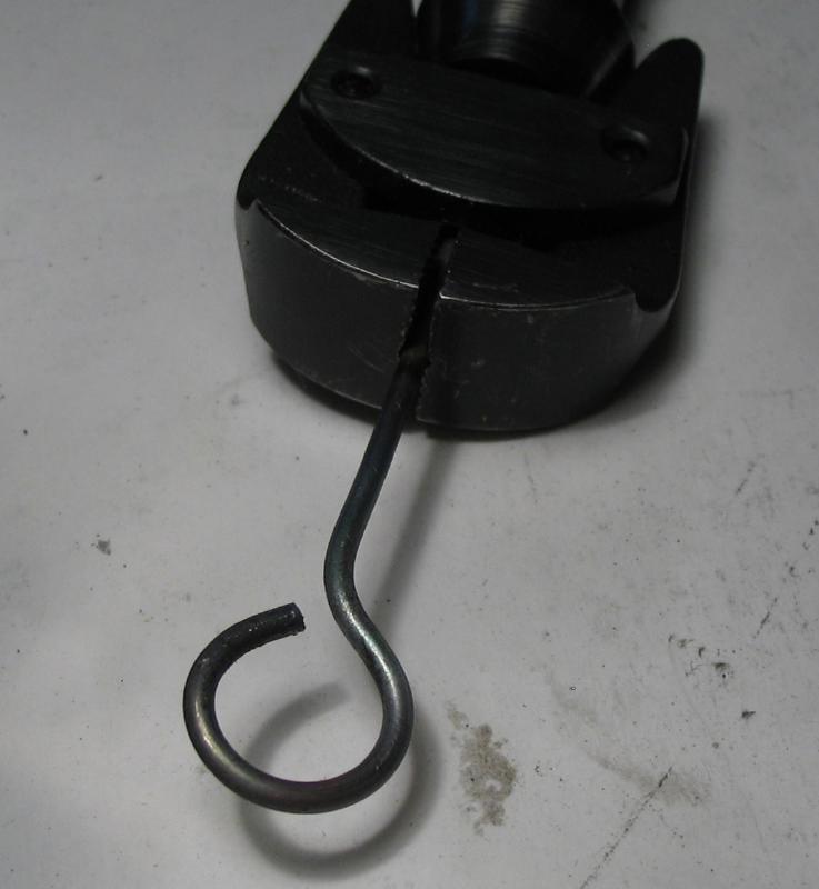
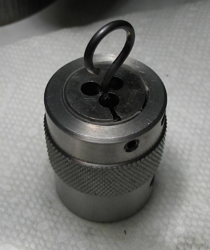
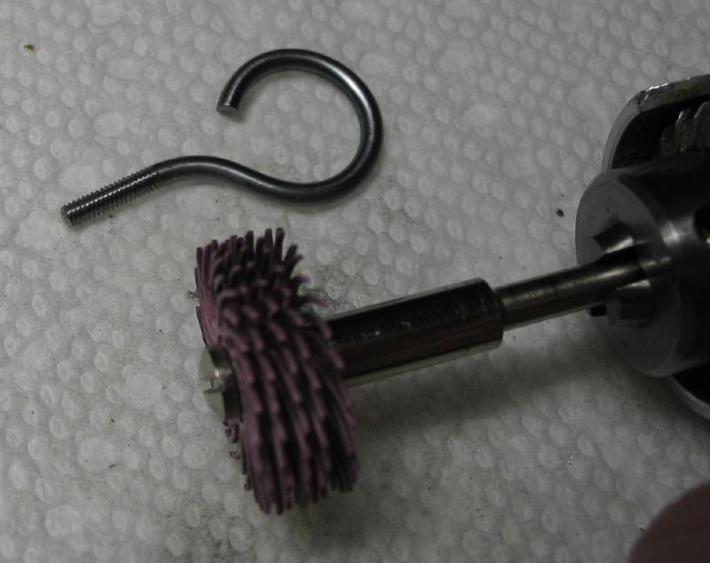
The tip of the hook was intentionally left too long as it is difficult to bend at the extreme end, but is simply sawed off afterwards. The hook is also sawed off with a surplus of length remaining that is filed to a slight taper to assist in starting in the M2 threading die. The threads were formed by manually driving into the die so the surplus length helps to keep the work upright while getting started and the surplus can be sawed off afterwards. The discoloration from heating (the rod was fairly dull to begin with) was removed with polishing brushes.
|
|
|

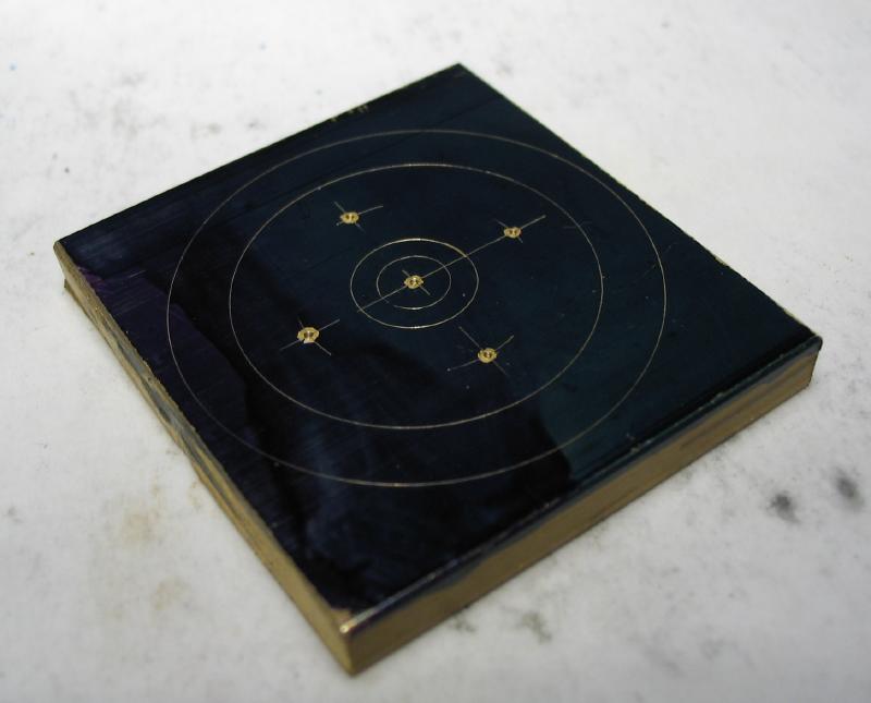
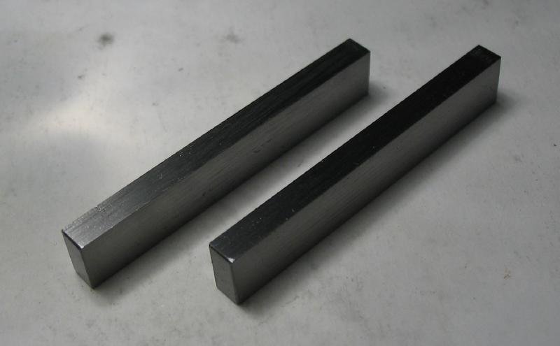
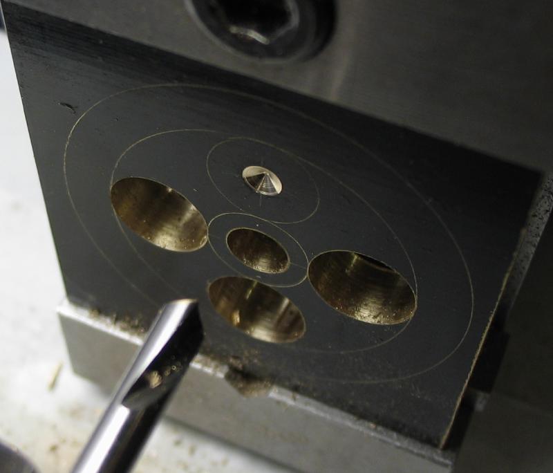
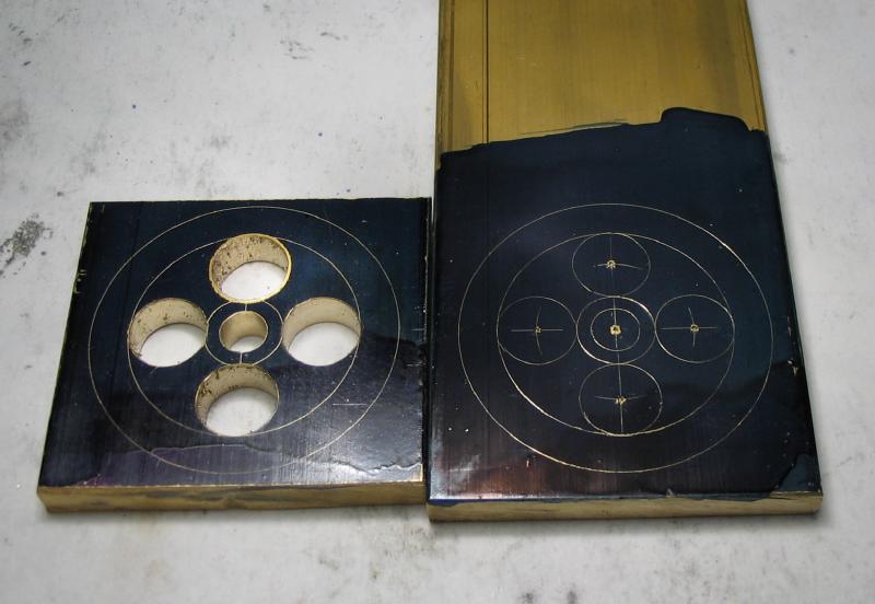
The pulleys were started from 1.5" brass plate. The positions for drilling were laid out and the parallel sides of the rough stock used to lay out and hold the work in the vise for drilling and reaming. A pair of 'parallels' made previously from 1/4"x1/8" tool steel stock were helpful in raising the work in the vise to allow the drills to pass through. The center punch marks were carefully found with a point, spot drilled, and then drilled in steps before finally reaming.
|
|
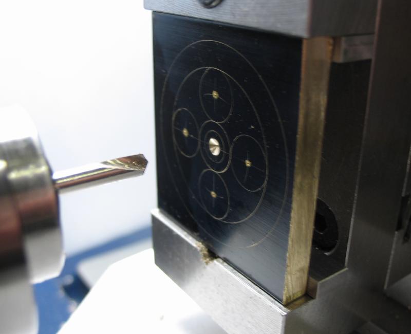
Forming the center bore.
|
|

|

|
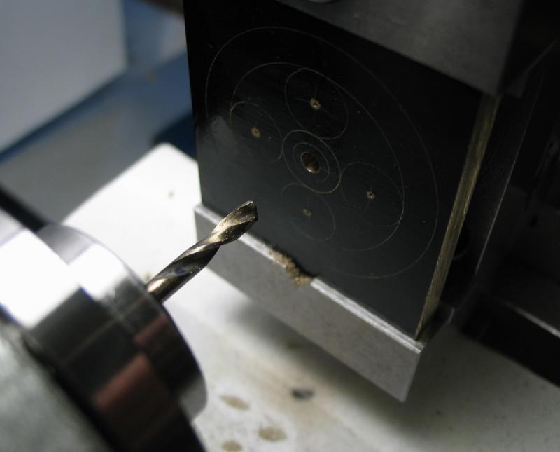
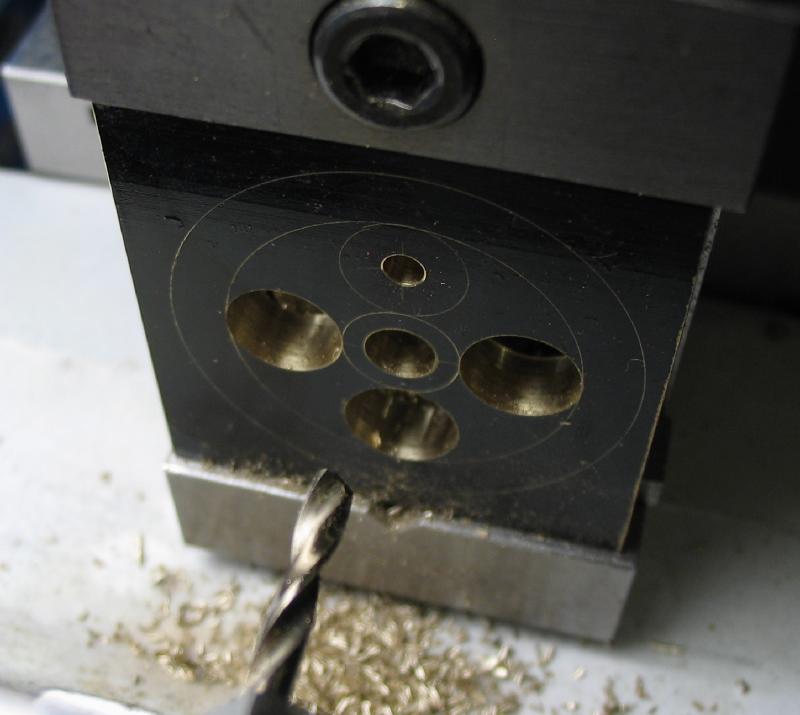
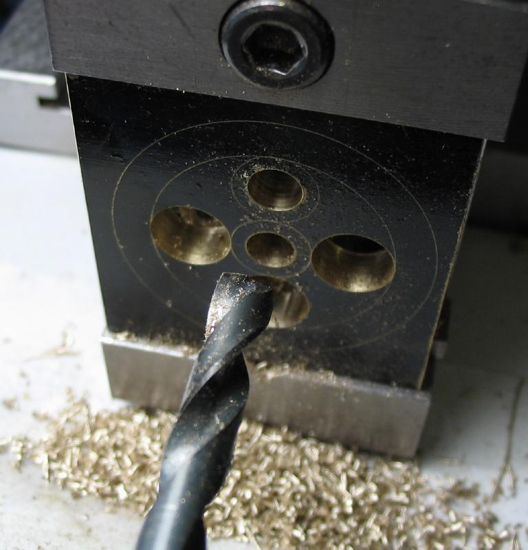
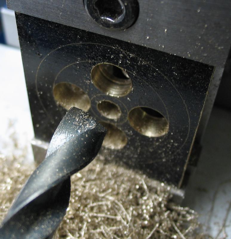
Showing all the steps in making a largish-sized hole. These larger holes are 5/16", so I started with 2.5mm, then 5mm, followed by a letter N-size drill bit, and then finishing with a reamer, which wasn't necessary with these larger holes in the pulley but the reamer leaves a much nicer finish than the drill bit.

|
|
|
|
|

|
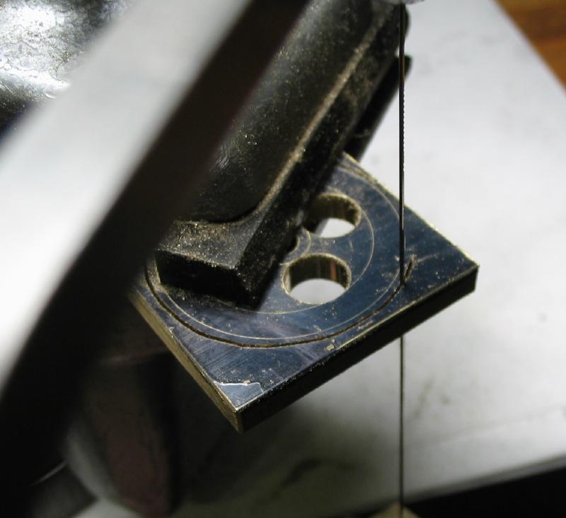
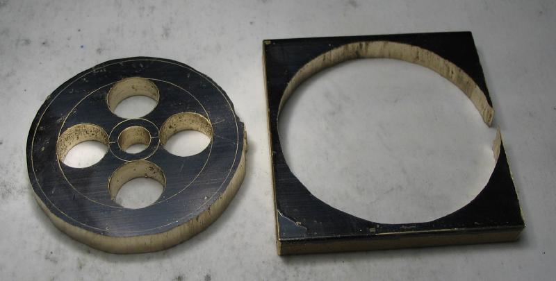
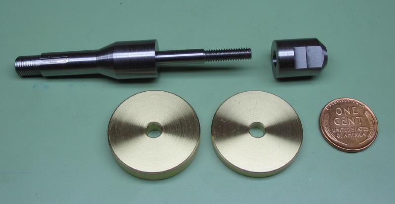
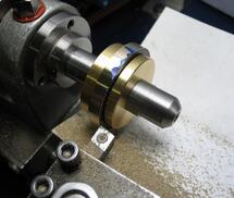
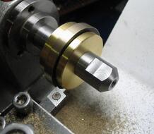
The pulley was sawed out to a roughly circular shape and brought to the required diameter and finished on the lathe. I took a small detour to make the arbor shown below. I added some details on its construction on the saw arbor page since it will hopefully find other uses. The brass washers were made with holding the pulleys in mind.
|
|
Some blue marker helps witness low spots that still need turning, and then brought to final diameter.
|
|
