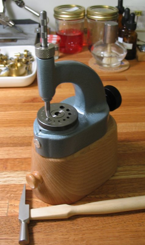
The Key Works
I am grouping together a few related components on this page, the winding arbor, setting arbor, and the key. Beginning with the winding arbor. For about the first decade or so of making watches, Daniels incorporated key winding (until he devised a unique alternative) into his watches. He makes a very opinionated statement (see the bottom of this page) regarding keyless winding, bordering on insult, and having worked on keyless mechanisms and always finding them annoying, I can only agree with his statements.
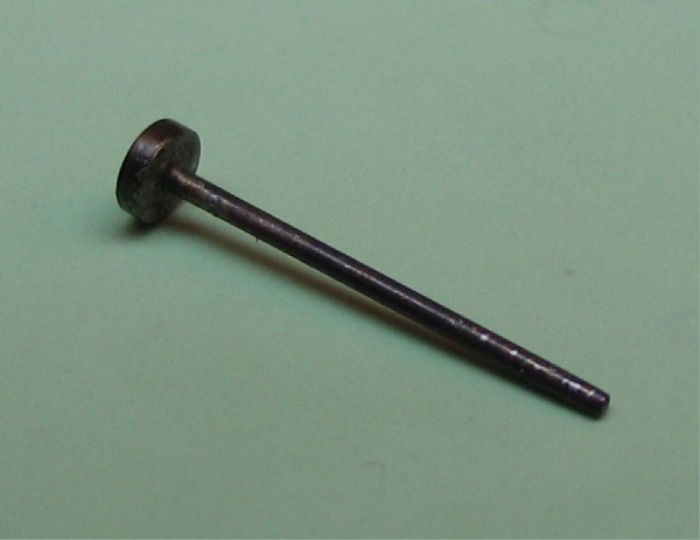
Winding Arbor
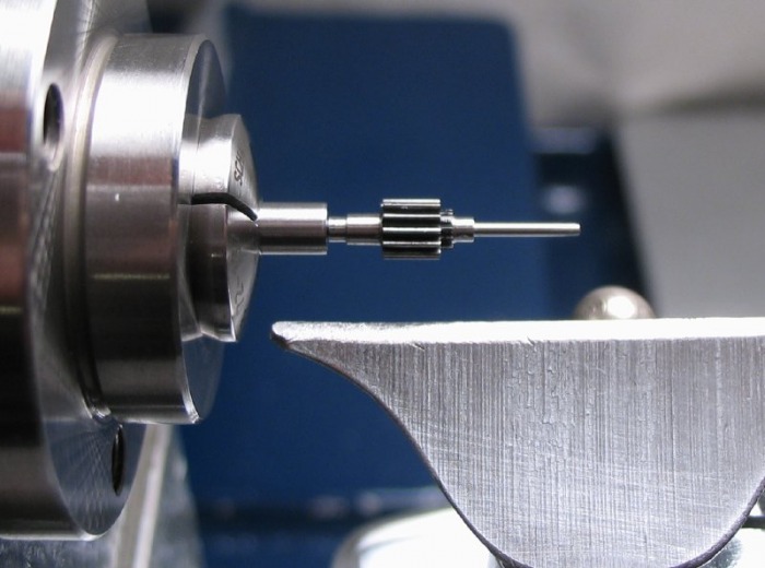
This is another component that Daniels doesn't spend much time discussing in 'Watchmaking.' I decided to make it while working on the stopwork finger pieces, since the arbor will also receive the same square-hole and I was generally satisfied with the results I was getting using the punch I made for the ratchet wheels and fingers.
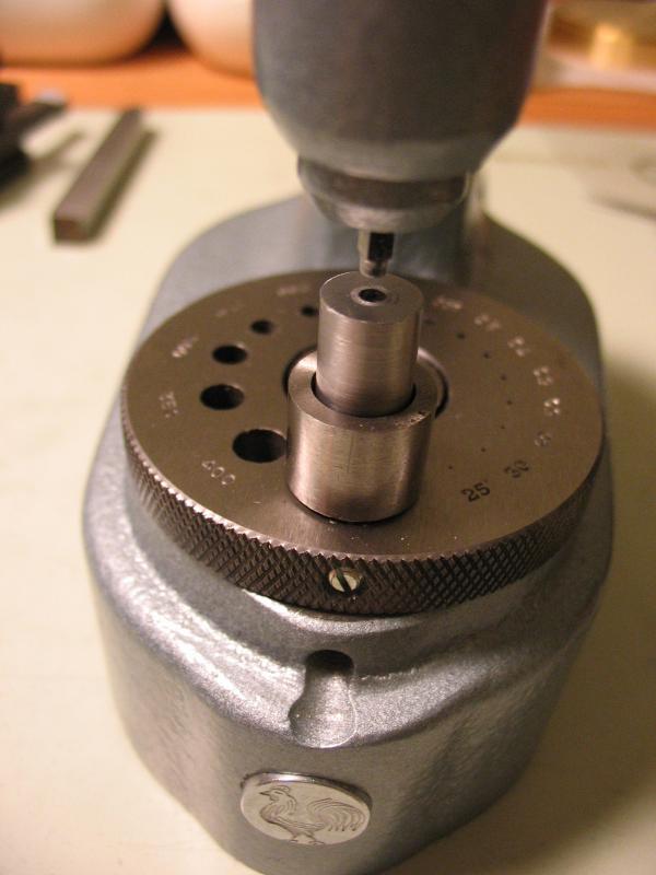
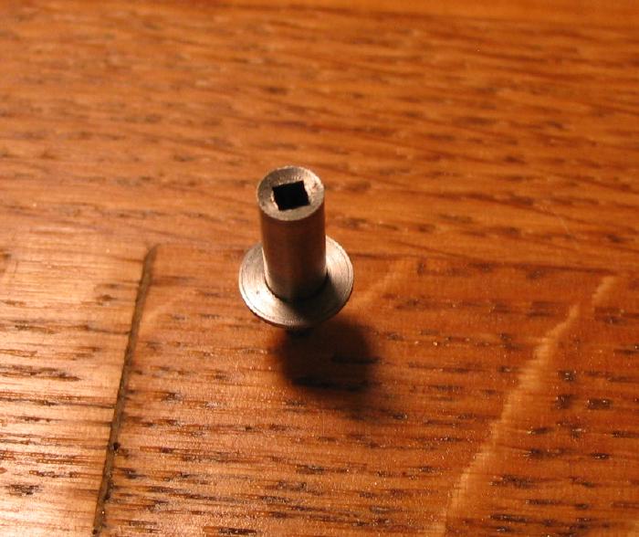
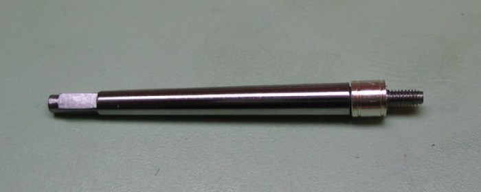
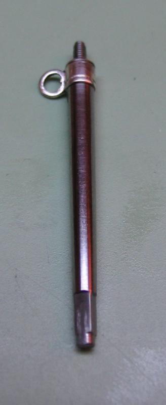
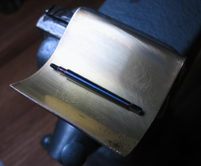
My winding arbor is based on the one that can be seen in the 'parts' photo of Plate III (1st edition). This is the only instance I can recall where this component can be seen in any sort of detail.
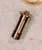
Taken from Plate III, Watchmaking 1981
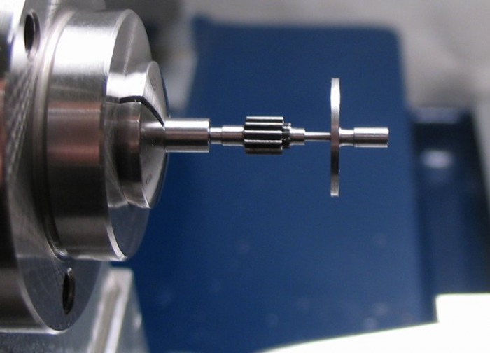
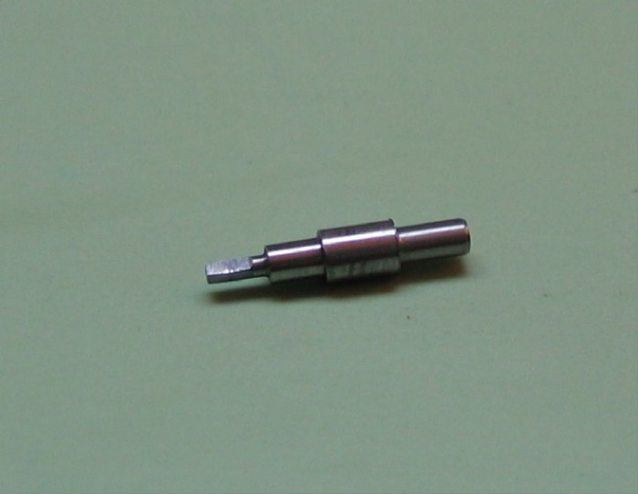
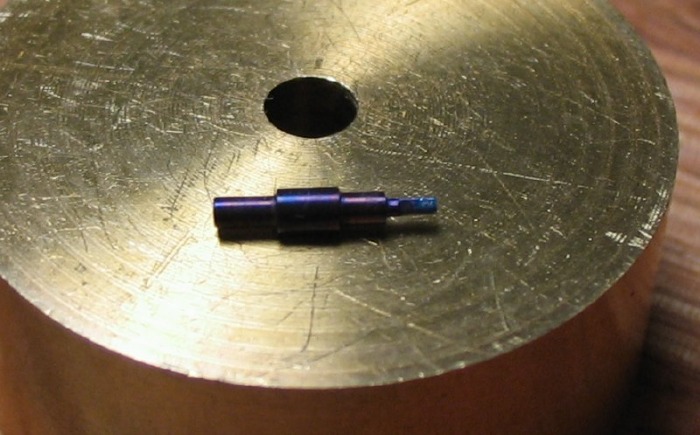
It has a square which mates to the third ratchet wheel and has a flange which is sandwiched between the ratchet wheel and the mainplate (most likely in a recess) and keeps the arbor in place. The shaft of the arbor goes through the mainplate and barrel bridge and is visible from the top, exposing the squared hole, which accepts the winding key. Taking some proportional measurements from Daniels's photos I came up with the dimensions for my arbor and can be found in the following link. I decided to make use of the same square punch from the ratchet wheels and finger pieces for making the square hole.
Click on the link below for complete dimensions in PDF format
| winding_arbor.pdf |
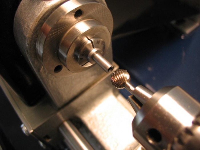
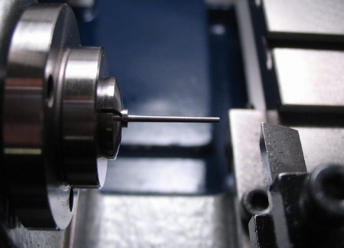
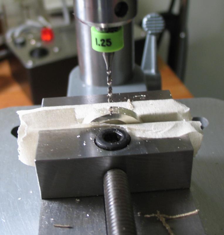
Turned a piece of 7mm drill rod down to 6.5mm and drilled the 1.7mm pilot hole for the square
Form the square using the broach
Of course things don't always go as planned. The hardened steel broach is quite brittle and does not tolerate any non-axial stress. The tip snapped off while prying it from the arbor. In the course of using this broach I realized why Daniels depicts making a small broach to fit into one of the staking punches, the broach and part can then be removed from the staking anvil and separated in a vice. So needing a new punch, I made one from 5mm drill rod that has a 2.5mm shaft to fit into a hollow end flat staking punch. It also must be hardened in oil. A little more detail is in the ratchet wheel post.
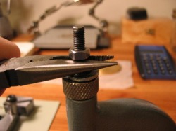
After breaking this broach as well, I came up with a different idea. I made a broach punch similar to my first (a full size staking punch) and threaded the top portion so that it can receive a nut that can be used to pry the punch out of the workpiece with pliers.
 |
 |
 |
 |
So enough about square broaches!
They are a pain in the neck, and the only time in watchmaking (thus far) where the use of significant force is a requirement.
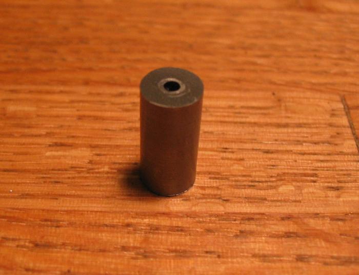
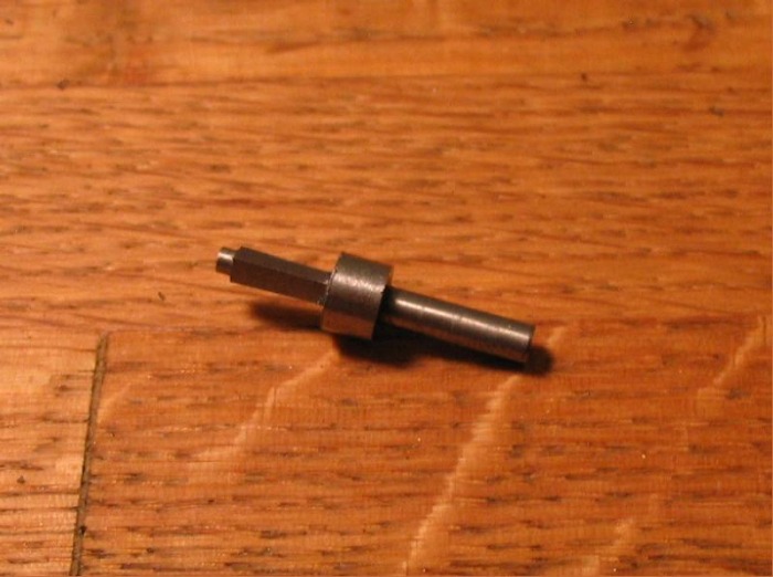
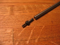
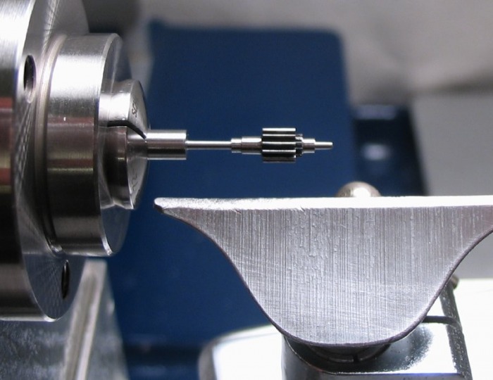
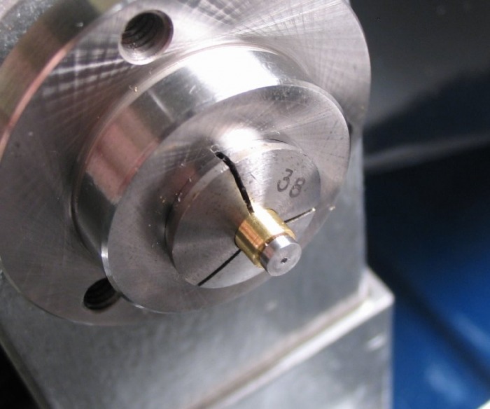
The square hole formed.

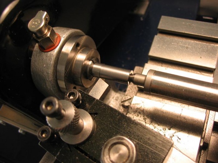
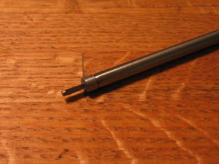
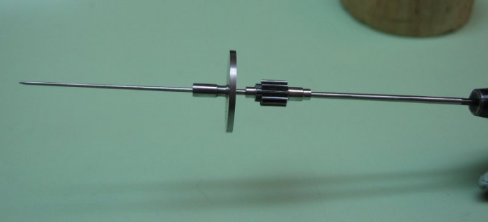
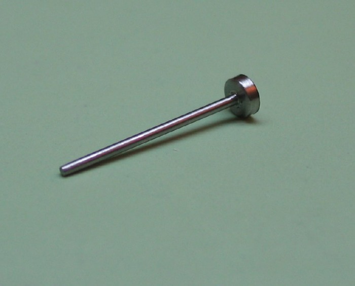
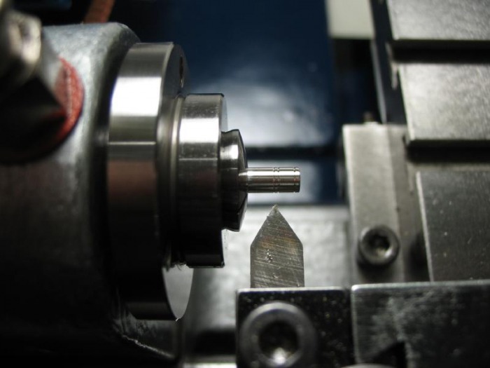
Turn the pivot portion of the arbor (3.5mm)
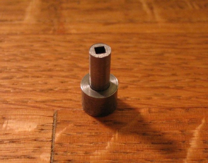
I then used a ¼" round carbide bur to form a concaved end. This is mainly a functional detail, so that the winding key will slip into the square, rather than slip off the winding arbor and scratch the barrel bridge.
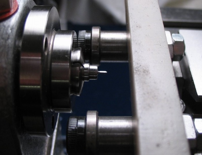
Using the roller filing rest the square shaft which mates to one of the ratchet wheels is formed. I used a No.2 Grobet hand file with a safety edge and finished with a No.6. The corners need to be relieved to make a true fit.
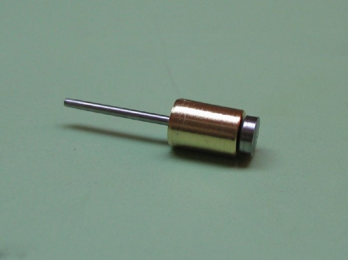
 Hardening Setup |
 Wrapped in iron wire |
Polishing the concave top of the arbor is done with a rounded brass rod. The rod is turned with a graver and the T-rest.
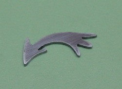
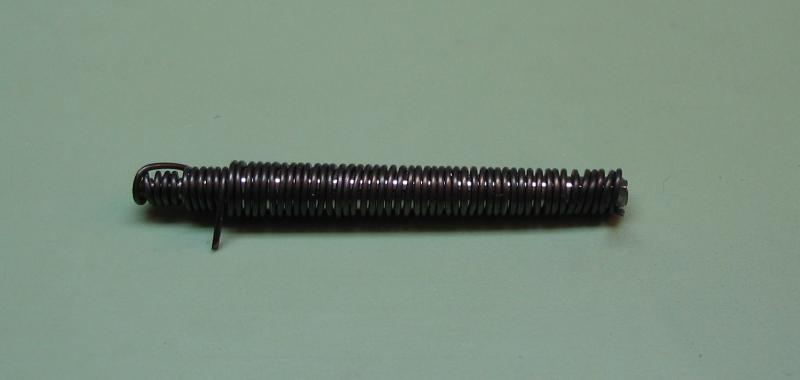
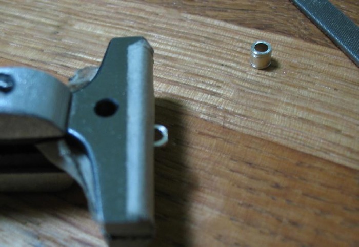
To prevent the owner winding the watch in the wrong direction, and to add a little whimsy to the aesthetics, a little arrow was sawn out of steel gauge plate. The arrow will be drilled to receive screws and then tempered blue to contrat with the brass barrel bridge. It will be placed just above the winding arbor.
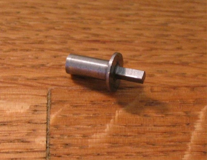
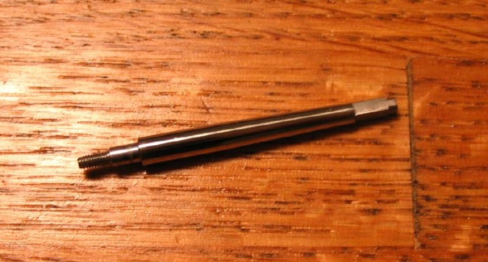
The Setting Arbor
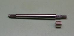
The center pinion was drilled and then broached forming a tapered hole. The arbor will be made to a tapangle to roughly match. The taper is turned so that the pinion will fit approximately 3/4 up to the flange, and then lapped to provide a good fit, but will still slip in place to allow for setting.
The cannon pinion (or cannon pawl in this case) is fit to the end of the arbor pin (with the center pinion fully set into position) in a similar manner, about 2/3 trial fit. This way it will securely fit when driven home. The cannon pawl will be fixed to the setting arbor by staking with support on a brass stump. Overall, it must be remembered that the arbor should have a friction slip in the center pinion but remain fixed on the cannon pawl.
The setting is accomplished with a setting key, smaller than the winding key, but requires another square hole to be formed in the head or setting arbor.
To begin, the center pinion and cannon pawl were placed onto the smoothing broach to check basic dimensions.
| minute_arbor.pdf |
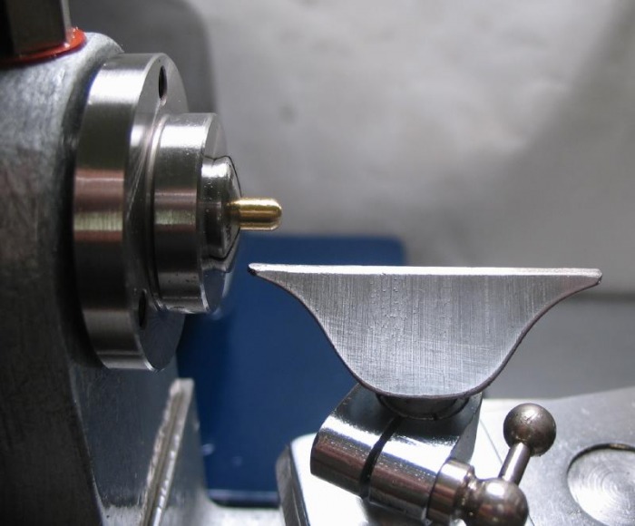
A matching taper is turned onto a length of 3mm O-1 drill rod. This taper is quite shallow, only about 0.5 degree. It is turned down until the center pinion just begins to fit upon it. At this point the reduction is made by lapping with a fine Arkansas slip stone. With great care it is continued until the pinion will reach a full seating, with friction, but still able to revolve on the arbor (with resistance).
The cannon pawl was lightly broached to fit the resulting taper, and provide a smooth fit for about 2/3rd of its height. This should allow the cannon pawl to be driven onto the arbor by staking to provide a tight fit. The pawl should not slip on the arbor, or in other words, the arbor and pawl should always turn together, whether during running or during setting.
The flange at the top of the arbor was turned with a graver to give a slight convex shape. This is to reduce/prevent friction, only the tapered portion should be involved with the works. The arbor was then parted off.
A brass pin was drilled and broached to match the taper of the arbor. This was used to then hold the arbor in the lathe to drill the key-hole (0.5mm).
 |
 |
The process of making a square hole must be undertaken, once again...
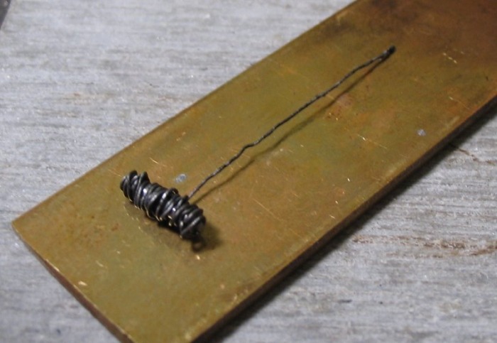
A square broach was made to fit the 2.5mm flat staking punch, it is made from 5mm O-1 drill and the broach portion was turned to 0.71mm and filed square using the file rest and a stone slip. It was stoned, since it is such a small size, a very fine file could have been used as well. The stone is a slower process, but is therefore less likely to remove too much too quickly and ruin it.
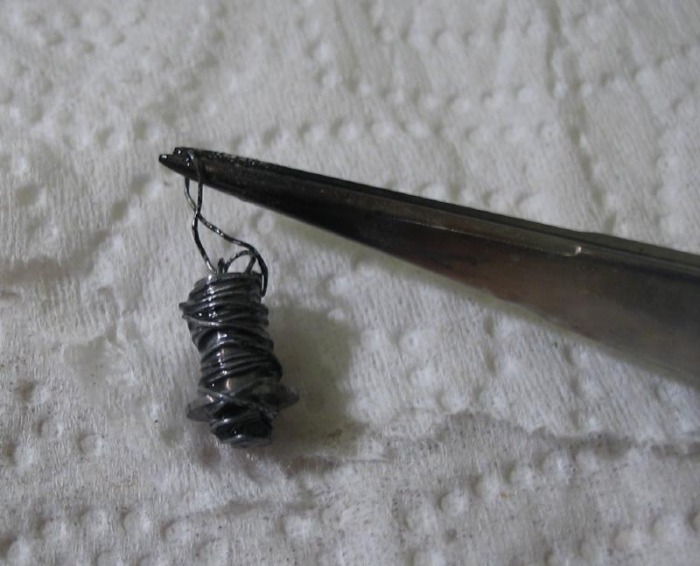
The square portion of the broach was wrapped in iron wire and fully hardened in oil. No protection (other than iron wire) was used, so it is completely blackened.
 Wrapped & Ready |
 Fully Hardened |
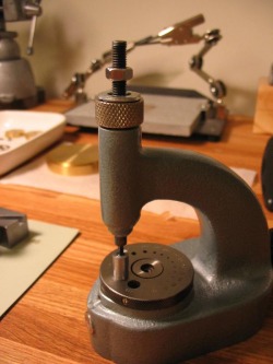
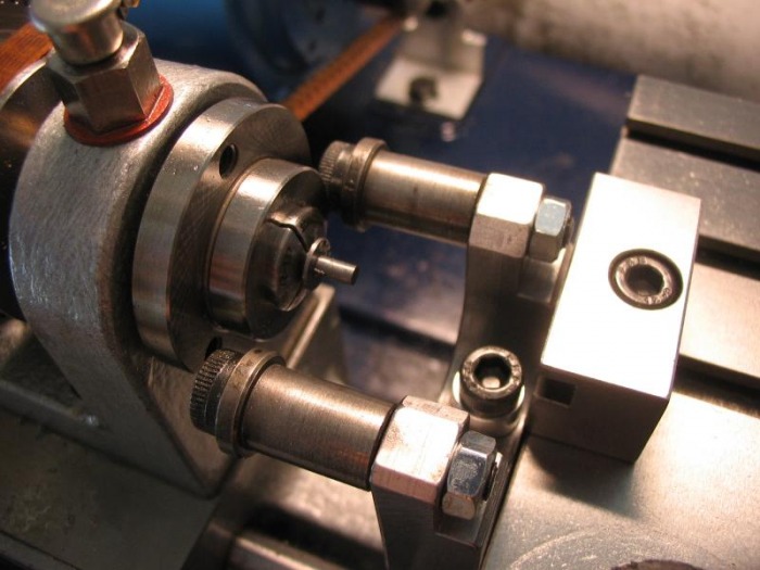
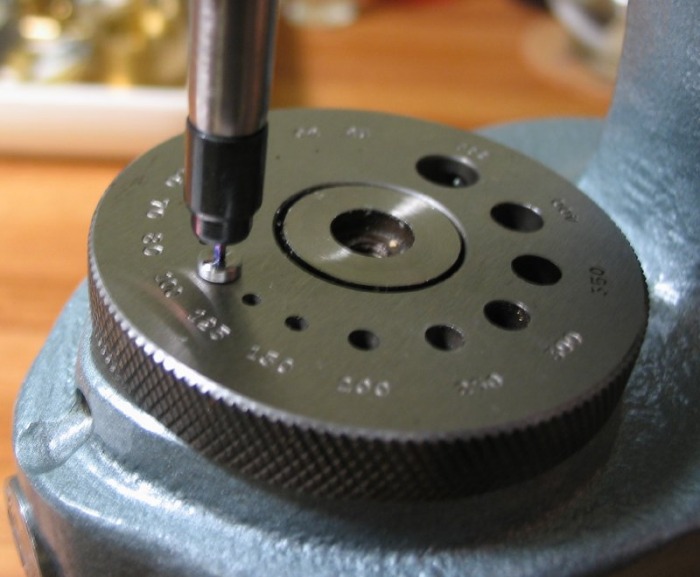
The arbor is then setup on the staking anvil, centered with the appropriate stake.
 |
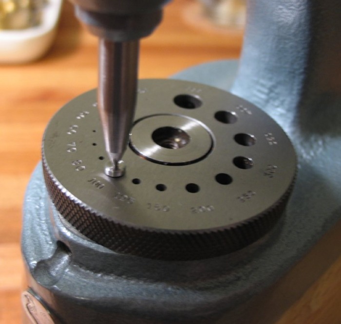 |
The flat punch is inserted and the square broach fit to the arbor using the small 0.5mm boss that was turned onto the end of the broach. One face of the broach was colored with a marker and a mark made on the top of the arbor to match, this way the broach can be removed, chips cleared, and re-inserted into the same position.
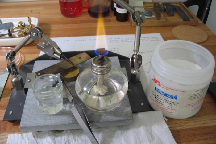
The arbor was tightly bound in iron wire, coated in boric acid and hardened in oil. It was then tempered blue on a bed of brass swarf in a small crucible (see center pinion finishing for details of this process).
To stake the cannon pinion or pawl onto the setting arbor and to remove the setting arbor from the pinion, a set of brass stakes/stumps were made to fit the jeweling press. The removal stump is simply made to surround the flange on the setting arbor and allows the arbor to be driven out from above with a pin punch. A cone shaped stump was made to fit the latter, the setting arbor is rested on top of the cone, in the square, and the cannon pinion can be driven onto the arbor.
 Removal stump |
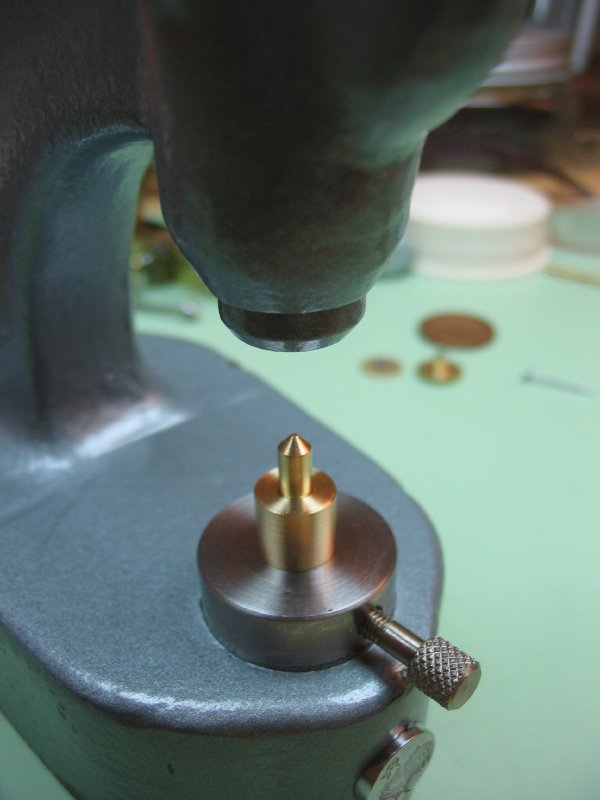 Staking stump (fits removal stump) |
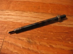
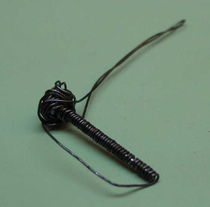
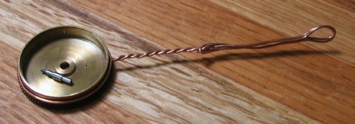
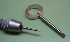
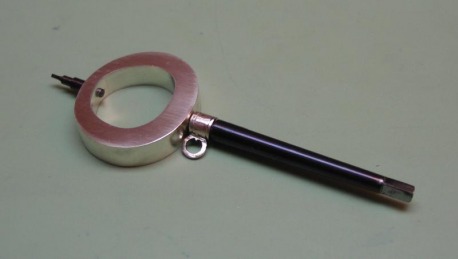
The Winding & Setting Key
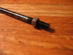
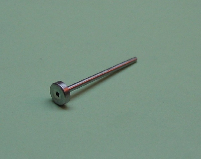
I didn't have the camera handy for the various stages of making the main shaft of the winding key, but it is fairly straightforward. I miscalculated the taper which was to go the length of the plain portion, so I may go back and re-turn it, or perhaps remake it ab initio as I have done with every other component thus far! It has a square to mate with the square hole of the winding arbor, and a 1.5mm threaded tip with a small plain portion. The threads will screw into the 'handle'. The short plain portion is for a collar that will be the connection point for a chain and will therefore fit loosely so that the key can rotate within the collar and not tangle up the chain.
The key is now hardened. It was wrapped in iron binding wire to help absorb oxidation and prevent distortion. To assist in preventing oxidation, the wrapped key was coated in boric acid. The boric acid is mixed into a slurry with alcohol. William Smith demonstrates this in one of his videos. The key was heated to bright red with a butane torch and then plunged into oil. Afterward the key is polished in preparation for tempering.
If you have read this far down the page then there is not much to say about making the setting key. It is made as if making a square broach to match the square made in the setting arbor above.
Wrapped in iron wire, ready to be coated in boric acid and hardened in oil.
Polished and ready for tempering. I made a simple blueing pan from an incorrectly made mainspring barrel (these scrap pieces come in handy for various, unpredictable things...) and fashioned a handle from copper wire.
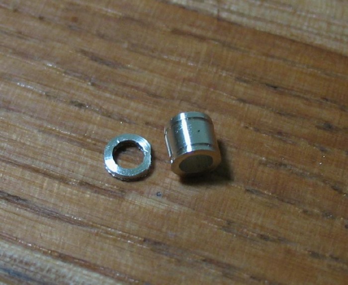
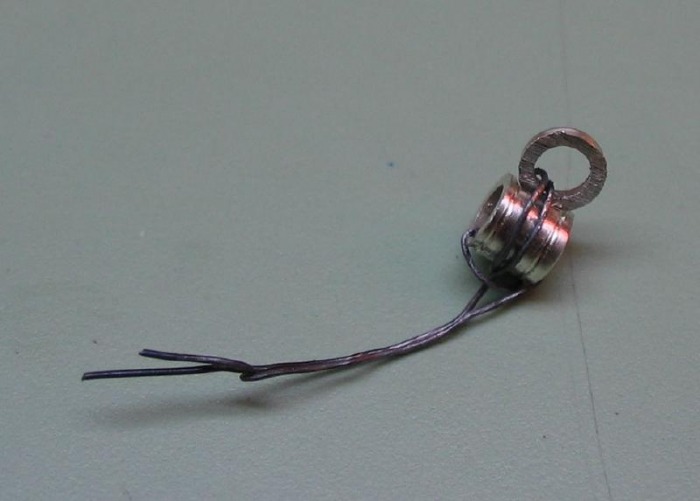
The collar is made from silver tubing. A couple decorative grooves are turned prior to parting off.
A piece of tubing is parted off to form the attachment point for the chain. A small flat is filed on the edge. It is wired in place with iron wire and the ring soldered.

The handle was started with a section of 6 gauge square silver wire. The wire was annealed to make it as malleable as possible, this needed to be repeated after any major changes and/or hammering. First the ends of the wire are formed on a ring mandrel, the ends will need to mate up for soldering. General methods for soldering and annealing, etc are described in more detail on the Chainmaking page.

After soldering, hammering, and filing we come to the desired shape.
The handle is drilled undersize to friction fit the setting key and drilled for tapping 1.5mm for the winding key.
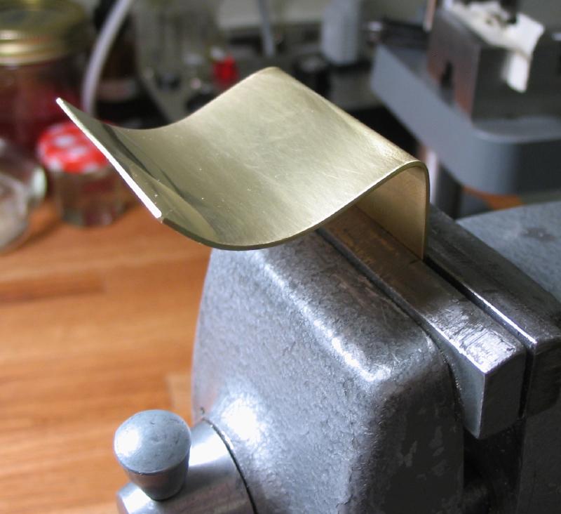
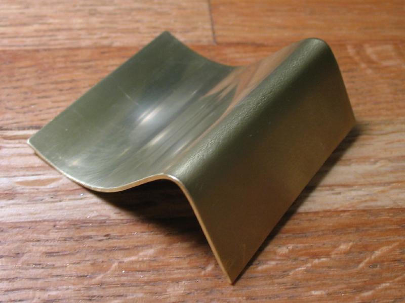
The key can now be tempered blue, for both its tensile properties and for its beauty. In Figure 87 of 'Watchmaking' Daniels gives an idea for a method of bluing long cylindrical objects (specifically winding keys). It was bent from a piece of brass plate. A steel rod was used to push on the end of the plate while heating to cause the key to rock back and forth, thereby distributing the heat and providing an even blue color.
 |
 |
The parts may now be fully assembled.
Daniels on Key Works (page 272, 1st Edition)
"... keyless, or stem-wound, watches are generally neat in appearance but difficult to wind. If they are easy to wind they are often clumsy in appearance. When the winding button is large enough to grip easily, it begins to dominate the case and influence the style of the watch. It is for this reason that after about 1860, with the advent of the quantity produced watch for people who seemed to care little for aesthetics and were apparently too feeble to use a key, the appearance of the watch degenerated into a tasteless and keyless, dull uniformity. The key-wound and the automatically wound watch can be designed wholly on aesthetic grounds without regard for the inclusion of a means of maintenance. A study of watches made since the early seventeenth century shows that the pendant always had style and elegance which echoed the beauty of the watch. The form of the keyless pendant is always decided by the winding button, but the increase in mass of metal draws the eye away from the dial. ... it is far better to make the dial more prominent by reducing surrounding distractions so that the watch will have greater elegance of functional purpose."
